Tracker
Tracking is a technique that involves analyzing the motion of an image over time. Silhouette provides multiple options for tracking: Point, Planar, Mocha and Flow.
• Point: Track one, two or four track points.
• Planar: Tracks several points (corners, edges and ridges) to define a plane.
• Mocha: Provides 2D transformation data by tracking planes rather than points.
• Flow: Uses optical flow to track a shape’s points.
Planar Trackers
Two planar trackers are provided: Mocha and Planar. Regardless of which one you use, the workflow is the same.
The key to getting the most out of the Mocha and Planar trackers is to find planes of movement in your shot which coincide with the object that you want to track. Sometimes it will be obvious--other times you may have to break your object into different planes of movement. For instance, if you were tracking a tabletop, you would want to draw a spline to avoid a flower arrangement in the center of the table, since it is not on the same plane and will make your track less accurate.
1 In the standalone, load some source footage and create a session using the Roto template.
or
2 In the plug-in, select Type > Roto when creating the project.
3 Make sure you are viewing and editing the Roto node by single-clicking on it in the Trees window or selecting it in the Node Selector at the top left of the Viewer.
Note: The Tracker is available as a separate node, but is also built into the Depth, Morph, Power Matte, Roto and Roto Blend nodes. This tutorial demonstrates the use of the Tracker from within the Roto node.
4 Go to the frame where you want to start tracking.
5 Set the View to Foreground for the fastest speed when tracking. In the Foreground view, no processing occurs and therefore it is faster than View > Output.
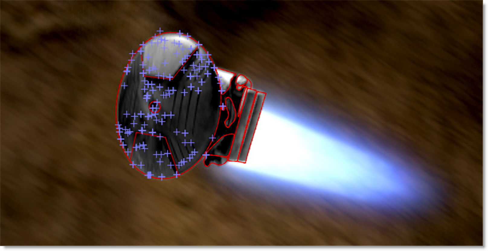
6 Create a shape around the object that you would like to track and make sure that there is some detail inside of the shape. It does not have to be exact and it is best to leave a little extra room around the object. In addition, you can use more than one shape as long as they are on the same geometric plane.
7 Choose the Tracker (Shift-T) in the Toolbar.
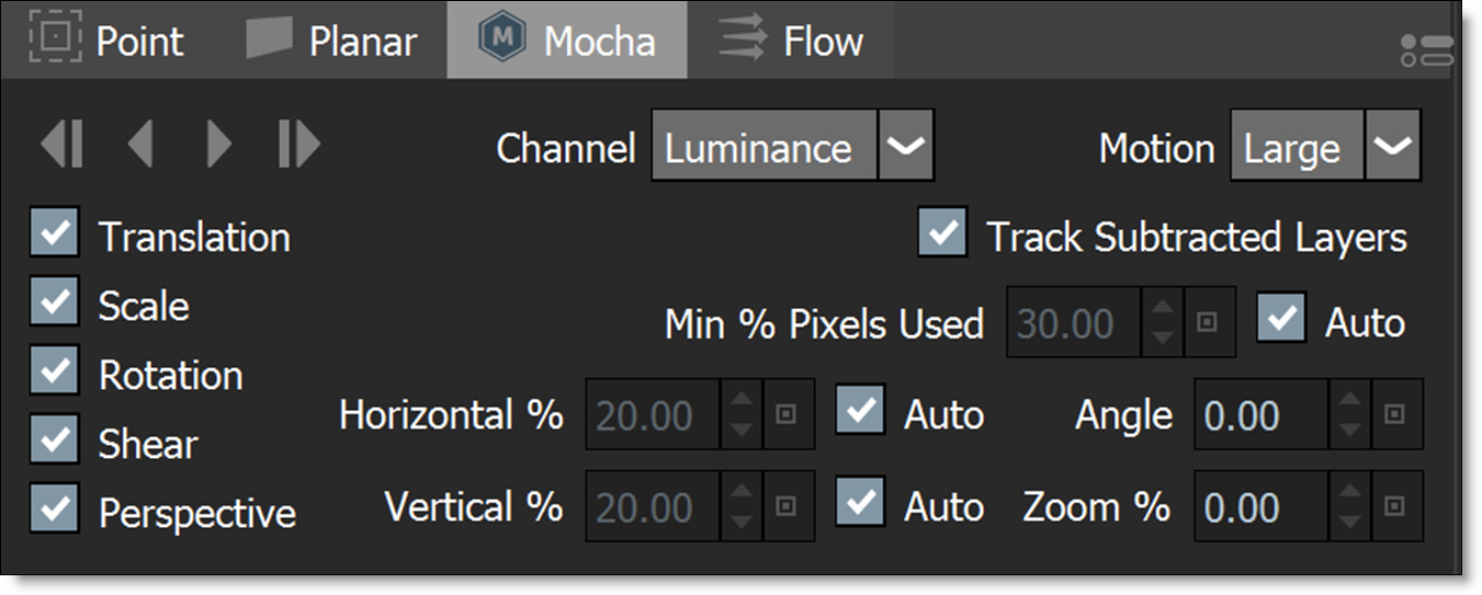
8 In the Tracker tab located at the bottom of the screen, select either the Mocha or Planar tab.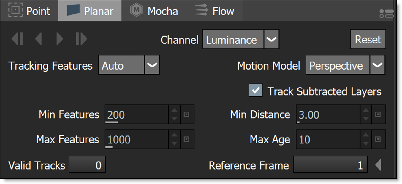
9 Enable Preview in Pre-Processing.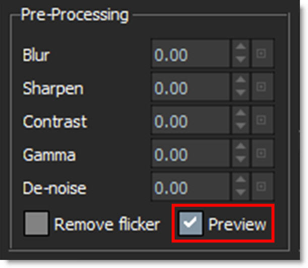
The image in the Viewer becomes black and white and displays the color space that you will track in.
10 Select the color space to track with in the Channel pop-up menu.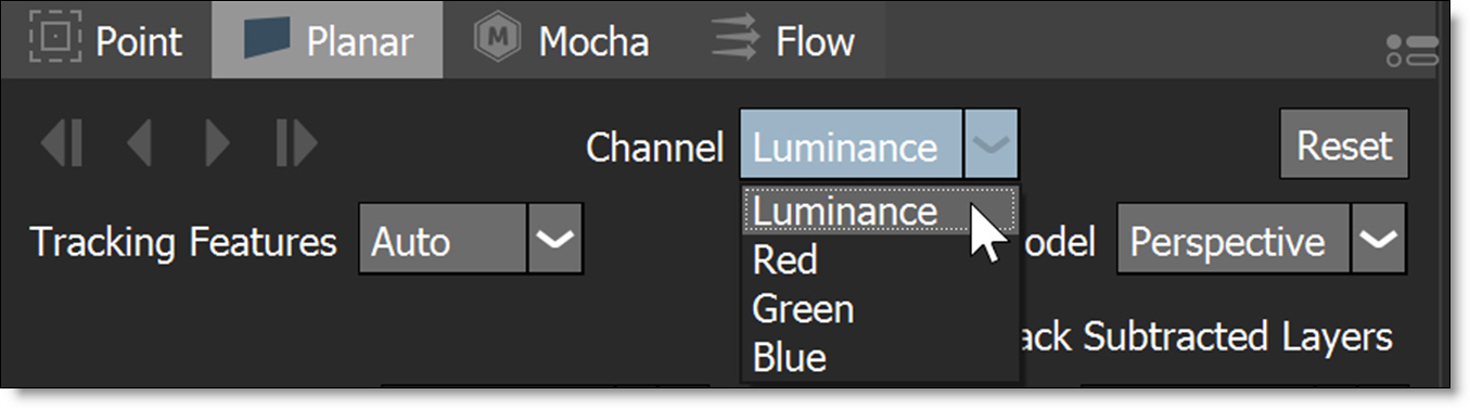
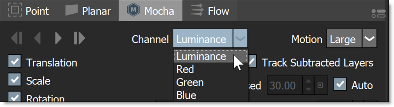
Pick the color space that displays the best contrast in the object you are tracking.
11 Disable Preview in Pre-Processing.
12 Select the tracking shape you created in the Object List.
13 Hit either the forward or backward track button depending on which direction you are tracking.
Both the Mocha and Planar trackers use layers to store the tracking data.
• If shapes are selected and not in a layer, clicking the Track Forward/Backward buttons will create a new layer, make it active and begin tracking.
• If shapes are selected in an unselected layer, clicking the Track Forward/Backward buttons will make the layer active and begin tracking.
14 When the tracking is done, that’s it, you're done.
The tracking data is automatically applied to the selected layer.
15 After tracking, if you are not happy with the results, try the different techniques listed in Planar Tracking Tips and Tricks and Mocha Tracker Tips and Tricks.
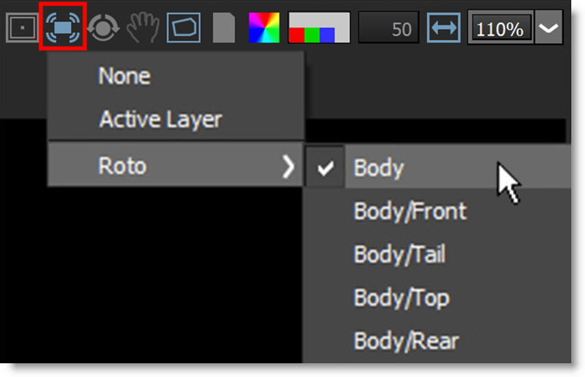
16 If you want to use Stabilization, click the Stabilize icon above the Viewer and choose either the Active Layer or a layer from the list. Available layers are organized by node.
The Viewer is now stabilized based on the selected layer’s tracking data.
17 Make shape adjustments and keyframe it as necessary using the Reshape and Transform tools.
18 When shape editing is complete, click on the Stabilize icon (if it was activated) and select None to turn it off.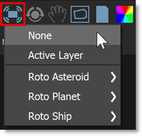
The Viewer is returned to its normal state.
Handling Occlusions While Mocha or Planar Tracking
In some cases, there are parts of an image that can interfere with the effectiveness of the Mocha or Planar trackers. To handle this, you can use exclusion areas while tracking.
Exclusion Area - To Be Tracked
An area of exclusion can be tracked simultaneously with the primary tracking area.
1 Create a shape around the object that you would like to track and place it in a layer. This will be referred to as the primary layer.
2 Create a shape around the area that you would like to exclude from the tracking process, place it in a layer and set the layer’s Blend mode to Subtract.
3 Place the subtractive layer above the primary layer.
4 Select both layers.
5 Make sure that Track Subtracted Layers is enabled.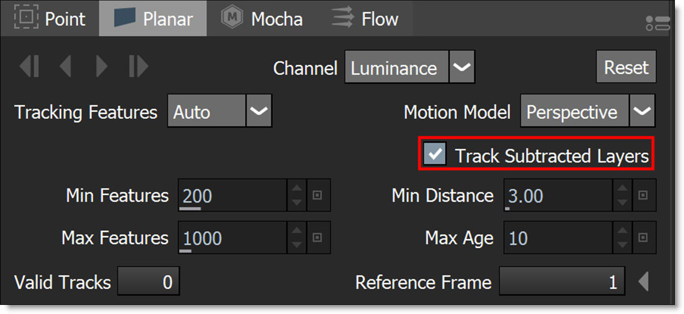
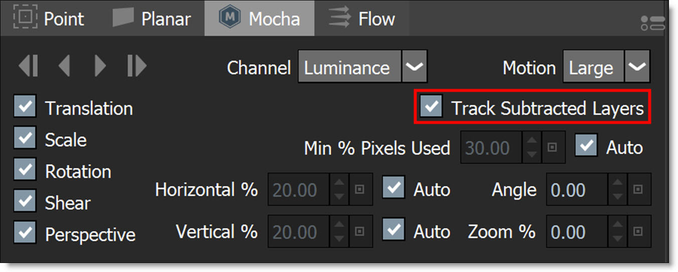
Note: If you don’t want to track the subtractive layer because 1) it was already tracked or 2) the shape was manually keyframed, disable Track Subtracted Layers.
6 Hit either the Track Forward or Backward button depending on which direction you are tracking.
Now the area within the subtract layer is not analyzed by the Mocha or Planar trackers when tracking the primary layer.
Exclusion Area - No Tracking
When an exclude shape should not be tracked by the Mocha or Planar trackers, create a subtractive shape above the primary tracking layer.
1 Create a shape around the object that you would like to track and place it in a layer. This will be referred to as the primary layer.
2 Create a shape around the area that you would like to exclude from the tracking process and keyframe it throughout the sequence. Set the shape’s Blend mode to Subtract.
3 Place the subtractive shape above the primary layer.
4 Select both the primary layer and the subtract shape.
5 Make sure that Track Subtracted Layers is disabled.
6 Hit either the Track Forward or Backward button depending on which direction you are tracking.
Now the area within the subtract shape is not analyzed by the Mocha or Planar trackers.
Offset Planar Tracking Using Layers
There are times when the object you are planar tracking becomes obscured, and in these instances, you can use a layer to compensate for the obscured object.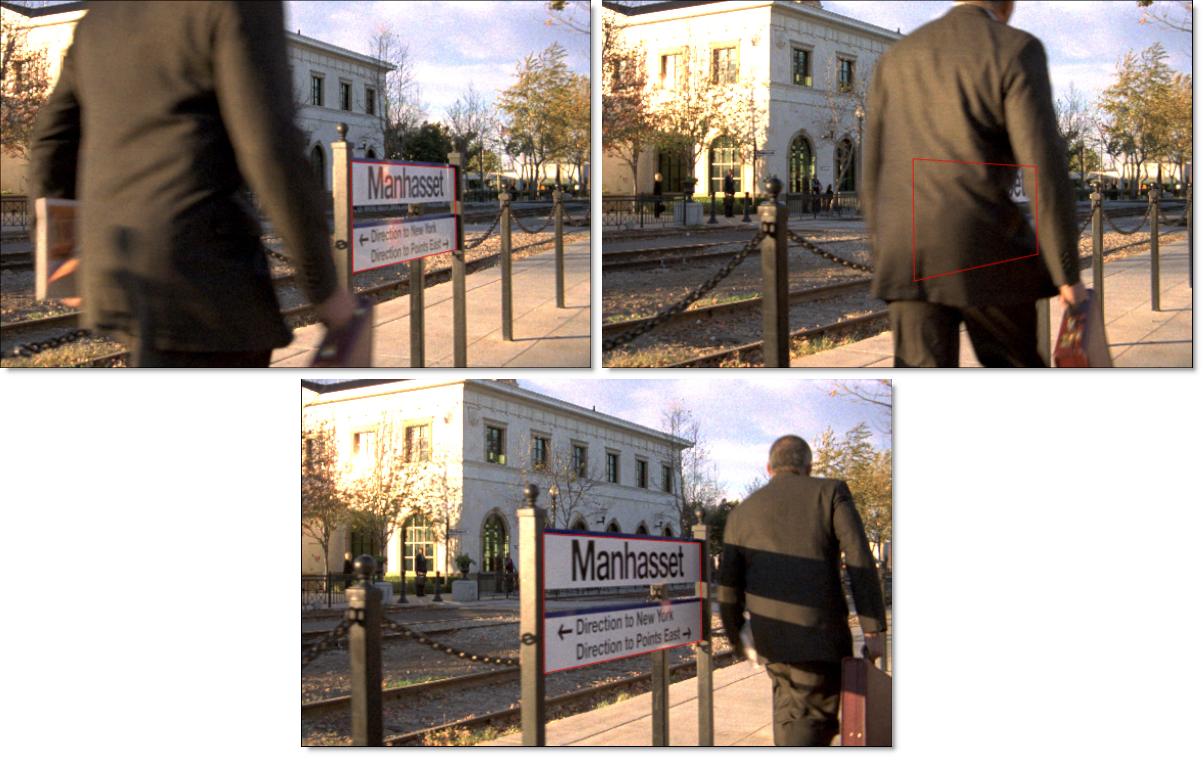
1 Track an object using either the Mocha or Planer tracker.
2 When the object you are tracking becomes obscured or the track fails, hit the Cancel button in the Tracker Progress window.
3 Back up to the last properly tracked frame.
4 Select the Timeline tab at the bottom left of the screen.
5 After this point in the Timeline, delete any Transform:Matrix keyframes for the tracked layer.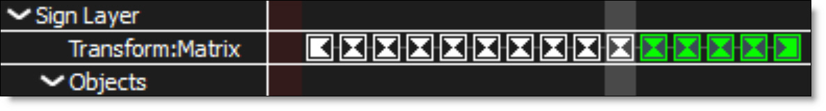
6 Click on Transform (T) in the Toolbar.
7 Set Transform keyframes for the selected layer at the last properly tracked frame by enabling the Animate icon for the layer parameters that you will be adjusting.
8 Move the Timebar forward to where the object you are tracking is no longer obscured and animate the layer parameters so that your shape matches the object you are tracking.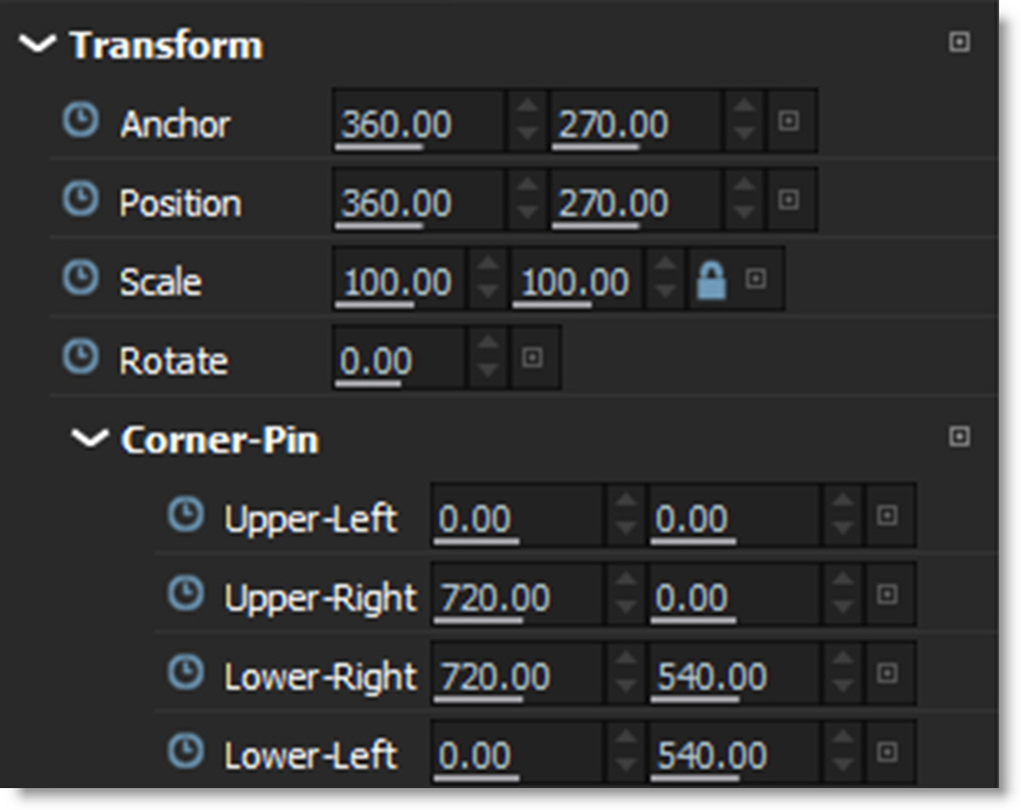
The manual keyframes you set take care of the animation of the object while the object was obscured.
9 Choose the Tracker (Shift-T) in the Toolbar.
10 If you are using the Planar tracker, press the Reset button to reset the track points to account for the new location. This sets a new Reference point.
11 Hit either the forward or backward track button depending on which direction you are tracking.
Smoothing Planar Tracked Layers
Smoothing planar tracked layers removes inaccuracies in the tracking data.
1 Select a layer which has been planar tracked.
Once selected, the layer displays tracking paths on the four corners and in the center of the frame.
2 Zoom into one of tracking paths on a corner of the image.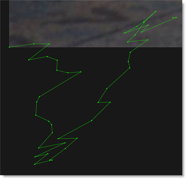
Viewing the path while adjusting the Smooth slider will provide visual feedback.
3 In the Tracker tab, choose Smooth and adjust the slider when it pops-up.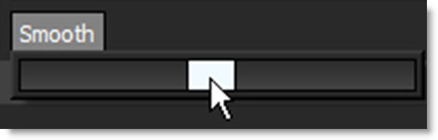
The planar tracked layer is smoothed.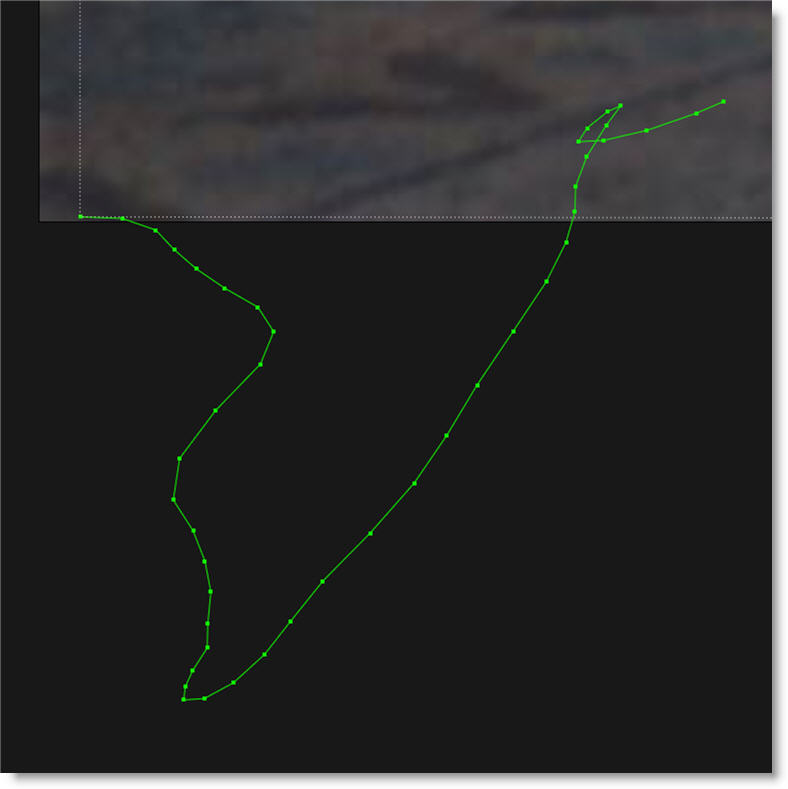
Group Tracking
Using the Planar tracker, multiple layers containing non-overlapping shapes can be tracked as separate planar surfaces.
1 Select multiple layers that contain non-overlapping shapes.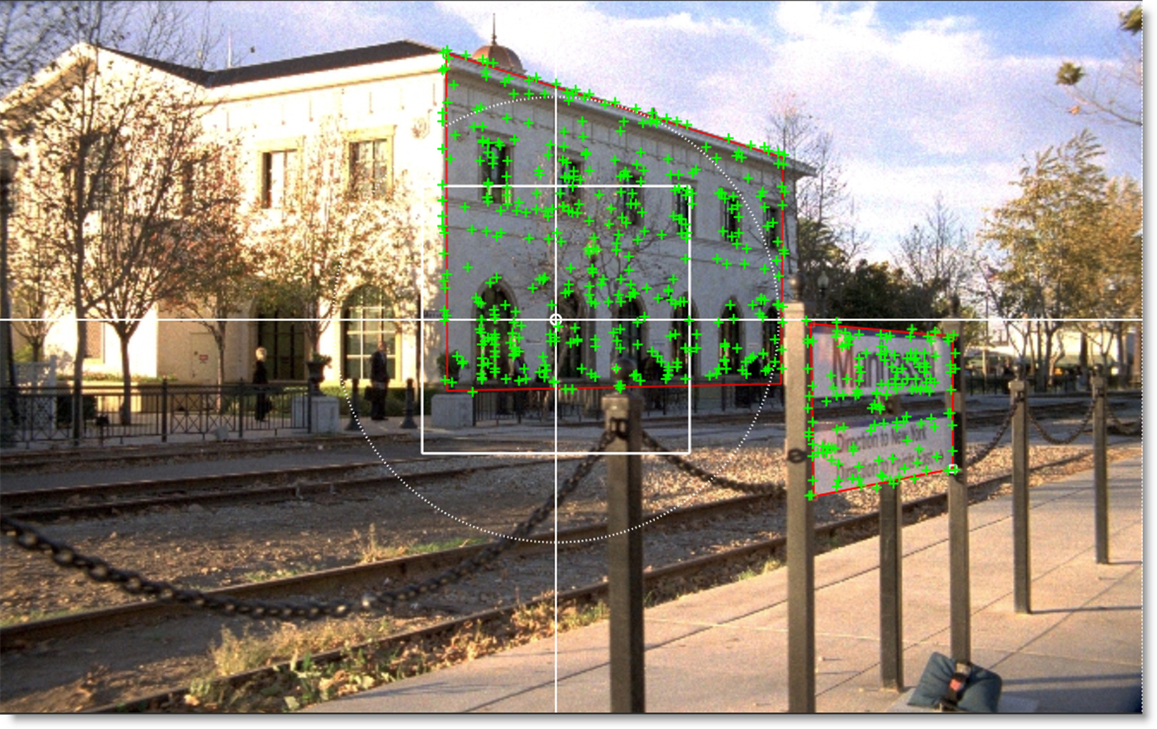
2 Track using the Planar tracker.
Each layer is tracked as a separate planar surface.
Part Tracking
Using the Planar tracker, Part Tracking uses multiple layers that contain overlapping shapes to aid in tracking non-planar surfaces.
1 Select multiple layers that contain overlapping shapes.
Make sure there is a good overlap between the shapes.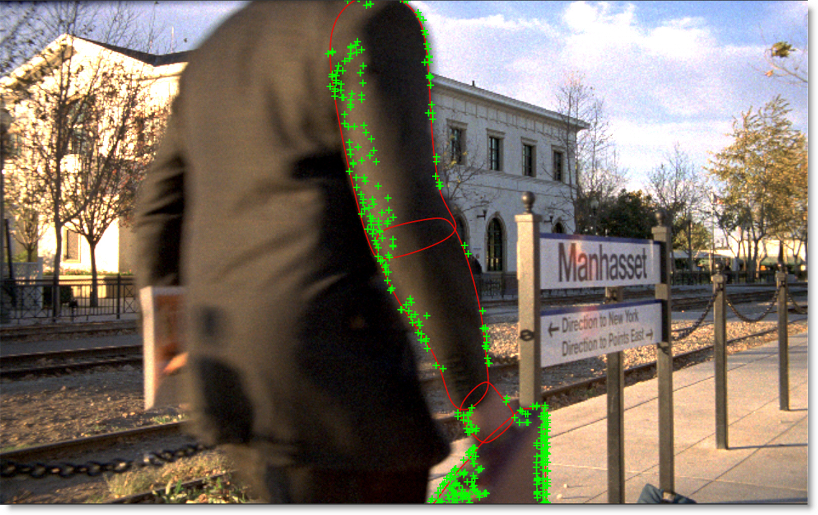
2 Track using the Planar tracker.
The overlapping shapes share coarse motion, but have individual motion at the fine scale. This is helpful when tracking non-planar surfaces.
Planar Tracking Tips and Tricks
If you have trouble tracking a shot using the planar trackers, here are some tips and tricks.
General Tips and Tricks
Scrub Your Timeline
When starting a track, go through your footage a few times to see what your best options are for tracking. You will save yourself a lot of time by making note of obstructions and possible problem areas in advance.
Change The Tracking Features
By default, Tracking Features is set to Auto which tracks corners, edges and ridges simultaneously and then automatically selects the best result. Changing from Auto to Corners, Edges or Ridges may yield a better result.
Switch The Motion Model
Perspective is the default motion model, but Affine (tracks translation, rotation, scale, and skew) or Translation (tracks the XY offset) may better choices for your clip. In general, use Perspective for tracking larger shapes, Affine for medium shapes and Translation for small shapes.
Use Edges
When tracking surfaces, you will usually get a much better track if you include the edges and not just the interior of an object. This is because the planar trackers can define the difference between the background and the foreground and lock on better.
Track From The Largest, Clearest Point
In order for planar trackers to keep the best possible track, it is usually best to scrub through the timeline and find the largest and clearest area to begin tracking from, draw your shape there, then use backwards and forward tracking from that point.
For example, if you have a shot of a sign coming toward you down a freeway, it is usually better to start at the end of the clip where the sign is largest, draw your shape and track backwards, rather than start from the beginning of the clip.
A Planar Surface Does Not Necessarily Have To Be Flat
We have a Planar racker which specifically tracks planes of motion, but this is not limited to tables, walls and other flat objects. Faces can be tracked very successfully around the eyes and bridge of the nose. Rocky ground, rumpled cushions, clumps of bushes, human torsos and curved car bodies are all good candidates. The key is low parallax or no obvious moving depth. When in doubt, try quickly tracking an area to see if it will work, as you can quite often trick the planar trackers into thinking something is planar.
Draw More Shapes
Remember you are not limited to one shape in a layer. Use a combination of shapes to add further areas or cut holes in existing areas to maximize your search.
Use Shapes Only For Tracking
You can use shapes for tracking purposes only and once the track is completed, you can hide or delete them.
Create Subtract Shapes
In some cases, there are parts of an image that can interfere with the effectiveness of the Planar or Mocha trackers. To handle this, you can create subtractive shapes in the area you are tracking.
Create a shape to subtract out areas of unwanted motion that may interfere with tracking and keyframe the shape as necessary. Place this shape above the layer that you are tracking and set the shape’s Blend mode to Subtract. Select the layer you are tracking and then add the subtract shape to the selection by using Ctrl/Cmd-click. Now when you track, the area within the subtract shape will be excluded.
Track From Different Points In Time
Depending on the motion of the object to be tracked, you may get better results if you track from the end to the beginning. You may also track from the middle to the beginning and then from the middle to the end.
Use A Different Channel To Track On
Change the Channel parameter from Luminance to Red, Green or Blue. The Channel parameter determines which image value the tracking algorithm uses.
Utilize The Pre-Processing Filters
Use the Blur, Sharpen, Contrast, Gamma, De-Noise or Remove Flicker pre-processing parameters.
Track The Foreground
Set the View to Foreground for the fastest speed when tracking. In the Foreground view, no processing occurs and therefore it is faster than View > Output.
There Is No Magic Bullet
The planar trackers are very flexible trackers and will save a lot of time, but you will eventually run into a piece of footage that just will not track. Large or continuous obstructions, extreme blur, low contrast details and sudden flashes can all cause drift or untrackable situations.
Mocha Tracker Tips and Tricks
In addition to the planar tracker Tips and Tricks previously mentioned, here is an important Mocha tracker tip.
When In Doubt, Ramp Up Your Pixels
You can quite often get a great result with the default settings, but if you’re getting a lot of drift, try setting the Min % Pixels Used value higher. The processing can be slower, but you will usually get a much more solid track.
Point Tracker
The Point tracker uses trackers which are placed on distinguishable image features.
Note: The Tracker is available as a separate node, but is also built into the Depth, Morph, Power Matte, Roto and Roto Blend nodes. This tutorial demonstrates the use of the Tracker from within the Roto node.
Creating a Tracker
1 Add a Roto node after the source image.
2 Select the Tracker (Shift-T) in the Toolbar.
3 Go to the frame where you want to start tracking.
4 Set the View to Foreground for the fastest speed when tracking. In the Foreground view, no processing occurs and therefore it is faster than View > Output.
5 In the Tracker window located at the bottom of the screen, select the Point tab.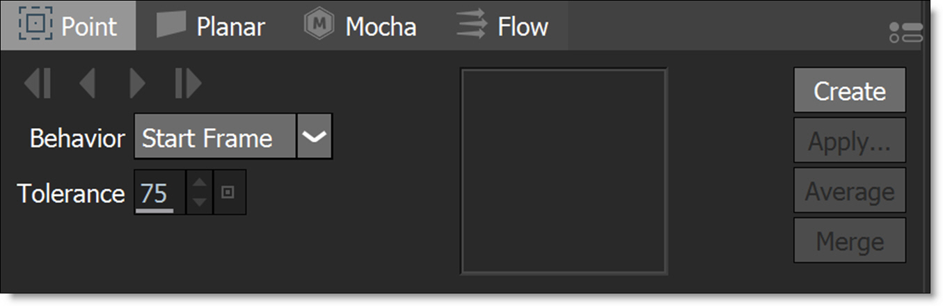
6 Press the Create button and a tracker is placed in the center of the image.
or
7 Alt-click on an open space in the image.
As you pass your cursor over the image with the Alt key depressed, a zoomed region to the right of the tracker aids in selecting your Match Area.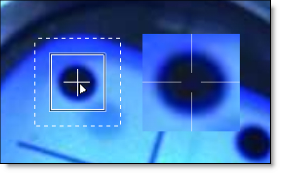
Moving Tracker Components
1 Clicking and dragging directly on the Track point will move all components of the Tracker: Match Area, Search Region and Track Point simultaneously.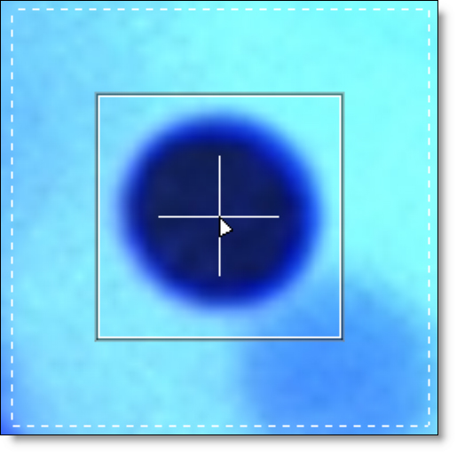
2 Clicking and dragging within the area of the Search Region will move only the Search Region.
3 Clicking and dragging within the area of the Match Area will move both the Search Region and Match Area simultaneously, leaving the Track Point at its current location. This would be used for Offset Tracking when the original track point becomes obscured.
Scaling Tracker Components
1 Clicking and dragging on the corners of the Match Area bounding box scales both the Match Area and Search Region.
2 Clicking and dragging on the corners of the Search Region bounding box scales only the Search Region.
Tracking an Image
1 Adjust the size and position of the Match Area and Search Region.
2 Right-click on the tracker and select the color space to use in the Channel sub-menu.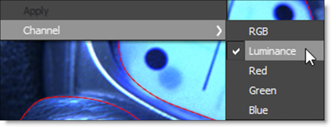
3 Hit either the forward or backward track button.
Silhouette will analyze the motion for each frame in the clip.
Offset Tracking
There are times when your original Match Area gets obscured, and in these instances, you can offset the Match Area and Search Region from the Track Point.
1 Create a tracker and track a portion of the clip until the Match Area becomes obscured.
2 Hit the Stop button in the Tracker Progress window.
3 Back up to the last properly tracked frame.
4 Click and drag somewhere within the Match Area and both the Match Area and Search Region will move simultaneously, leaving the Track Point at its current location.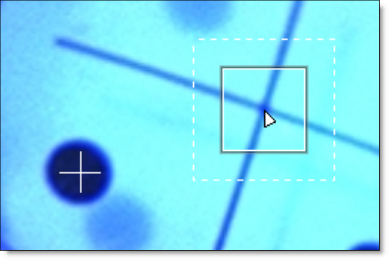
5 Click the forward tracking button to continue tracking.
The Track Point follows the same path, but the new Match Area is used to acquire the tracking data.
Tracking Difficult Shots
Some clips are difficult to track because of erratic motion or the occlusion of the feature that you are attempting to track. In these cases, you can do a bit of hand tracking using one of two methods:
• By pre-keyframing the tracker at various frames throughout the clip.
• Keyframing a shape and then creating tracker keyframes based on the shape’s motion.
Keyframing the Tracker
1 Create a tracker.
2 Adjust the tracker to match the object at various frames throughout the clip.
3 In the Tracker tab, change the Behavior to Key Frames.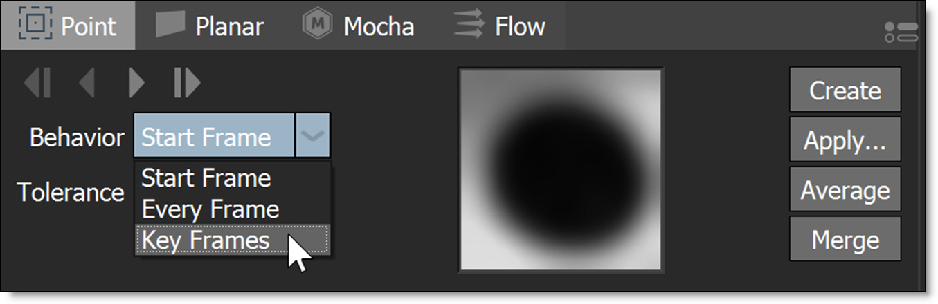
The Tracker Match Area will now use these keyframes as a reference while tracking.
Create Tracker from Shape Center
1 Create a shape around the feature that you would like to track. Go to various frames throughout the clip and adjust the shape to match the feature.
2 Select the Tracker tool and right-click on the shape.
3 From the pop-up menu, select Create Tracker from Shape Center.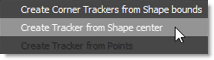
A tracker is automatically created around the center point of the shape and any shape keyframes are automatically applied to the Tracker.
4 In the Tracker tab, change the Behavior to Key Frames.
The Tracker Match Area will now use these keyframes as a reference while tracking.
Modifying Tracking Data
Averaging Trackers
Averages multiple tracks into a new destination track. A common technique is to track forwards from the first frame to the last, and then create a second track, tracking backwards from the last frame to the first. These two trackers are then averaged together to derive a more accurate track.
1 Select more than one tracker.
2 In the Tracker tab, choose Average.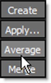
A new averaged tracker is created.
Smoothing Trackers
Smoothing trackers removes inaccuracies in the tracking data.
1 Select a tracker to smooth.
2 Zoom into the tracker’s path.
Viewing the path while adjusting the Smooth slider will provide visual feedback.
3 In the Tracker tab, choose Smooth and adjust the slider when it pops-up.
The tracker is smoothed.
Merging Trackers
If you have multiple trackers that cover different frame ranges, they can be merged into one tracker, automatically compensating for the different offsets.
1 Select multiple point trackers that cover different frame ranges.
For instance, you may have one tracker that covers frames 1-25, another 25-75 and the last one from 75-100. Ideally, the trackers should overlap in time by at least one keyframe.
2 Click the Merge button.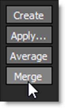
A new tracker is created that covers the frame range encompassed by the three trackers.
Applying Point Trackers
Match Moving and Stabilizing Layers
In general, tracking data should be applied to layers instead of individual shapes. The tracking data is copied into the transform of a layer (containing shapes) allowing you to have separate keyframes for both the layer transformation and for the shapes. This results in far fewer shape keyframes than other methods and is the preferred way of working with clips in motion. The result is a very flexible method for discrete editing of layer and shape transformations.
Once applied to a layer, the tracking data can be used in Match Move or Stabilize mode. In Match Move mode, the clip moves as normal and the shape follows along according to the tracking data. In Stabilize mode, the clip is locked in place by stabilizing the Viewer. In either mode, you only need to keyframe the shape when it changes form.
1 Select the trackers that you would like to use.
2 Press the Apply button.
• With only trackers selected, clicking Apply creates a new layer and the tracking data will be applied to that layer.
• If a layer is selected along with the trackers, the tracking data will be applied to the selected layer.
You have a choice of applying position, scaling and/or rotation. However, scaling and rotation require two trackers.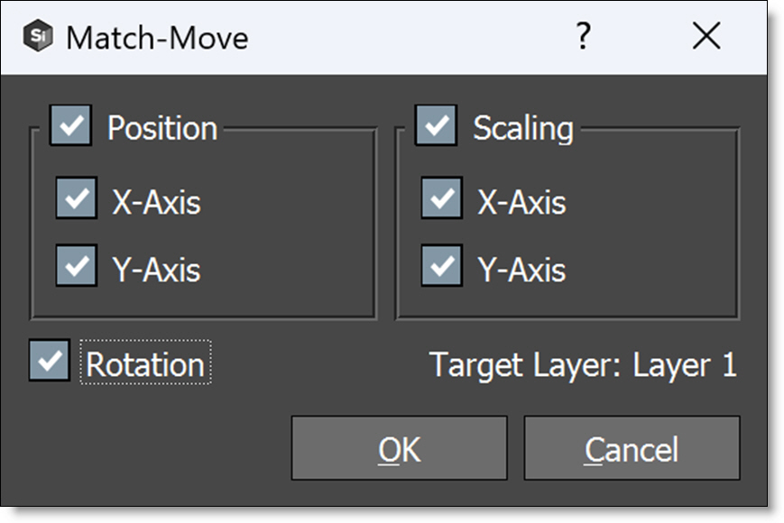
3 Select Position, Rotation and/or Scaling and click OK.
The tracking data is applied to the Layer’s > Transform > Matrix parameter.
4 Create a shape inside of the layer.
If you look at various frames in the clip, you’ll see that the shape is match moved to the motion of the image.
5 If you want to use Stabilization, click the Stabilize icon above the Viewer and choose either the Active Layer or a layer from the list. Available layers are organized by node.
The Viewer is now stabilized based on the selected layer’s tracking data.
6 Make shape adjustments and keyframe it as necessary using the Reshape and Transform tools.
7 When shape editing is complete, click on the Stabilize icon and select None to turn it off.
The Viewer is returned to its normal state.
Each layer can have different tracking data applied to it. Just go to the Tracker tab and apply the motion from other trackers to other layers.
Four Point Corner-Pin Tracking
Four-point tracking is traditionally used to match the perspective of a square or rectangular shape by tracking its four corners and applying a corner-pin transformation.
1 Create four trackers on the corners of a square or rectangular object and track the motion.
2 Create a layer in the Object List using the Add Layer icon.
The new layer is active and you can tell by the check mark icon in the box to the right of the layer name in the Object List.
Note: Point tracking data is only applied to the active layer.
3 Select the four trackers.
4 Press the Apply button.
The corner-pin data from the four trackers is applied to the layer.
5 Create a square shape inside of the selected layer. When drawing the shape, it should be placed near the location of the four trackers.
If you look at various frames in the clip, you’ll see that the shape’s motion is matched to the motion of the image.
Match Moving Points
Match moving applies the motion of a tracker to individual points on a shape.
Note: Match moving individual points results in keyframes being set on every frame of the shape and can make it cumbersome to later edit those points. This functionality has been added to Silhouette as some users prefer to work with this way.
1 Select a tracker.
2 Click on a shape to select it and then select a point.
Note: To select points on a shape, you must first select the shape by clicking on the shape outline. Then, Ctrl/Cmd-click each point that you would like to select. Also, when a tracker overlaps a point, it will be difficult to select the point while in the Tracker. To select a point that overlaps a tracker, switch to the Reshape tool, select the point and switch back to the Tracker.
3 Right-click over a selected point and choose Apply from the pop-up menu.
The tracking data is applied to the point.
Point Tracker Tips and Tricks
If you have trouble tracking a shot using the Point Tracker, here are some tips:
• Set the View to Foreground for the fastest speed when tracking. In the Foreground view, no processing occurs and therefore it is faster than View > Output.
• Stop the tracker, go to the bad frame and reposition the Track Point, and hit the tracking button again. You don't need to go back to your start frame.
• Lower the Tolerance value, and track again from the beginning, or the frame before the bad frames. The lower the Tolerance, the more forgiving the tracker will be--but also less accurate.
• Start over and switch Behavior from Start Frame to Every Frame. This means that instead of trying to compare the tracking region with the first “pure” frame, it will try to match to the previous frame. If you re-track from the middle of a clip, it will consider your new start frame as your reference frame with either setting.
• Use the Blur, Sharpen, Contrast, Gamma, De-Noise or Remove Flicker pre-processing parameters.
• At any time, you can manually adjust the Track Point by simply grabbing it and putting it where you need to.
• Change the Channel parameter from RGB to Luminance, Red, Green or Blue and re-track. The Channel parameter determines which image value the tracking algorithm uses.
• A technique you can use to assist with difficult shots is to manually insert tracking keyframes. For example, if you have 100 frames to track, you can put in a keyframe every 5 or 10 frames by repositioning the Tracker. Once your keyframes are manually entered, return to frame 1 and set the Behavior to Key Frames. The tracker searches along the tracker's pre-existing motion path to find matching patterns.
• You can use the same technique as in the previous tip, but with the following differences. Create a shape around the feature that you would like to track. Go to various frames throughout the clip and adjust the shape to match the feature. Select the Tracker tool and right-click on the shape. From the pop-up menu, select Create Tracker from Shape Center. A tracker is automatically created around the center point of the shape and any shape keyframes are automatically applied to the tracker. In the Tracker window, change the Behavior to Key Frames. The tracker Match Area will now use these keyframes as a reference while tracking.
Flow Tracker
The Flow tracker uses optical flow to track a shape’s points and requires either an Optical Flow ML, PowerMesh Warp or a ST->Flow node connected to the Roto Data input port.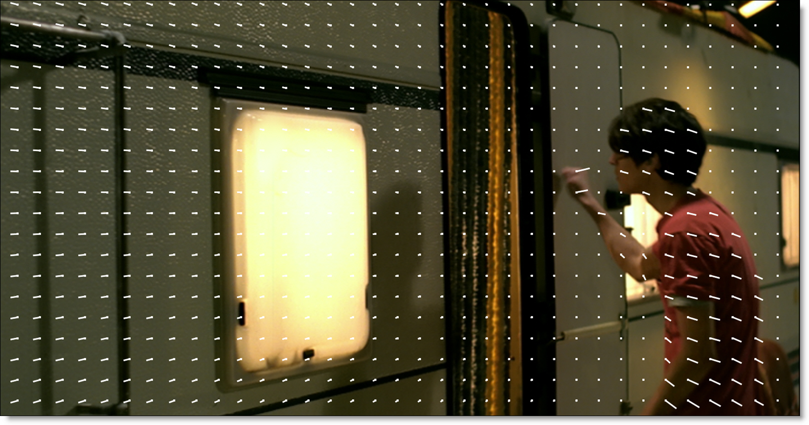
The Optical Flow ML node estimates per-pixel motion between frames and can be used to track shapes and objects. Forward or reverse vectors as well as a colorized representation of the motion can be displayed in Viewer.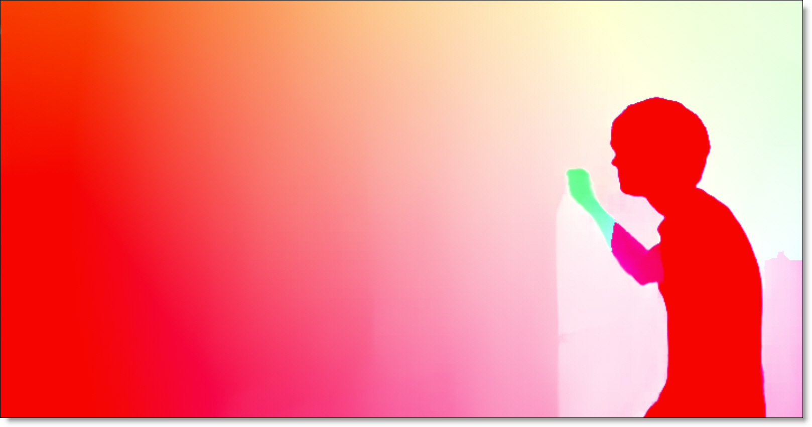
Shape Flow Tracking
1 Add a Roto node after the source node.
2 Go to the frame where you want to start tracking.
3 Create a shape around the object that you would like to track.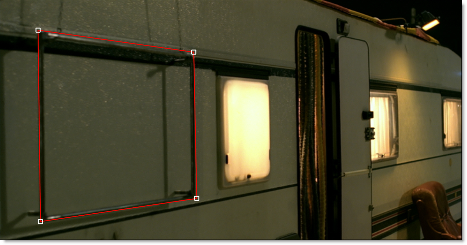
It is important that the shape’s points fall within an area of motion. Otherwise, the shape’s points won’t move when tracked.
4 Choose the Tracker (Shift-T) in the Toolbar.
5 In the Tracker tab located at the bottom of the screen, select the Flow tab and click the Create Optical Flow ML Node button.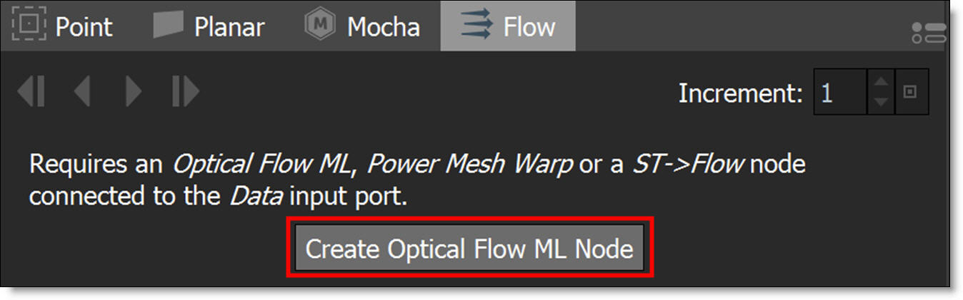
An Optical Flow ML node is automatically created and connected to the source with its Data output connected to the Data input of the Roto node.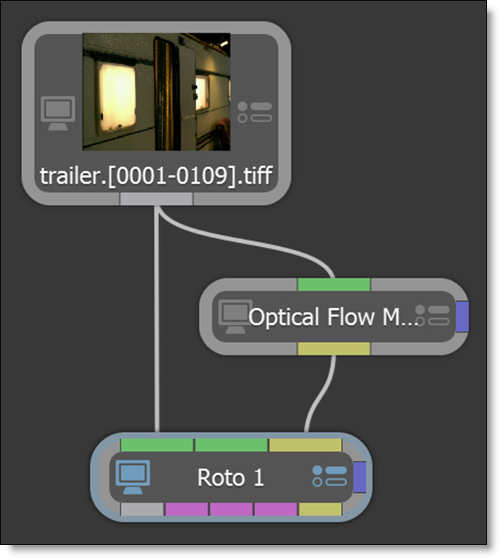
6 Set the Increment parameter.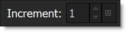
Increment sets the keyframe frequency when tracking. Set shape keyframes on every frame, at an interval or for the current frame using the K shortcut key. The K shortcut key can also be used in the Transform and Reshape tools.
7 Hit either the forward or backward track button depending on which direction you are tracking.
Note: The Tracker Direction buttons are only enabled when there is a Data input and a shape selected.
As tracking progresses, the optical flow data is used to track the shape’s points.
8 If the shape drifts or is not accurate enough after tracking, fine tune the result by setting additional shape keyframes and re-run the track.
When more than one keyframe is present prior to tracking, the tracker uses both forward and reverse tracking resulting in a more accurate track.
Tracked Layer Flow Tracking
The Flow tracker can be used in conjunction with a Point, Planar or Mocha tracked layer.
1 As described in the last tutorial, use Roto and Optical Flow ML nodes.
2 Select a previously tracked layer.
3 Create a shape within the tracked layer.
4 Select the Tracker tool and in the Flow tab, hit either the forward or backward track button depending on which direction you are tracking.
When a shape is selected within a tracked layer, the Flow tracker tracks the remaining motion.
Handling Occlusions While Flow Tracking
In some cases, there are parts of an image that can interfere with the effectiveness of the Flow tracker. To handle this, you can use exclusion areas while tracking.
1 Add a Roto node and create a shape around the area that you would like to exclude from the Flow tracking process.
2 Either keyframe the shape manually or track it.
3 Hook the Roto node’s output (far left output port) to the Obey Matte input (right edge of node) of the Optical Flow ML node.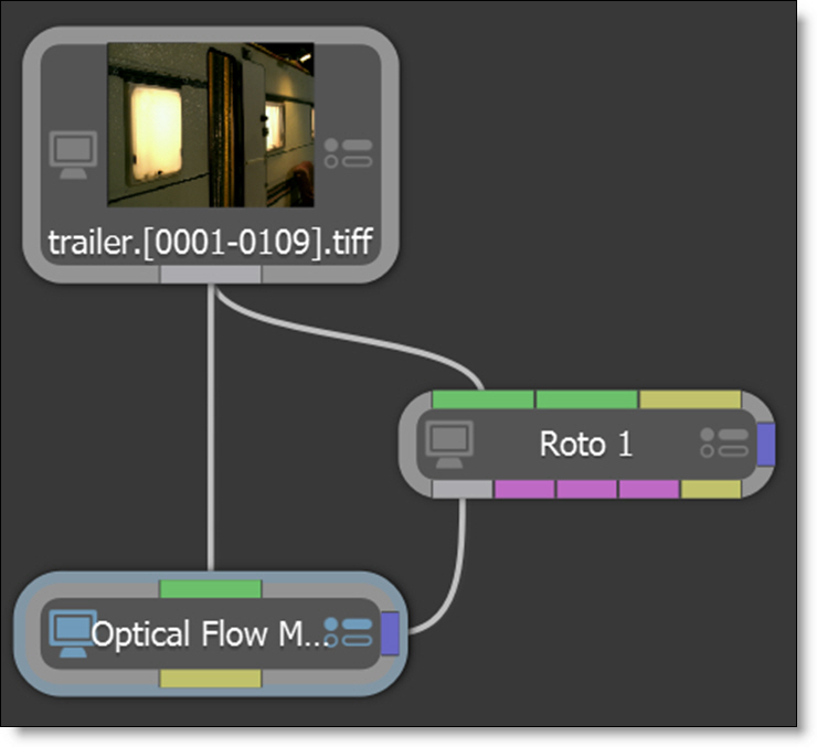
4 Select the Optical Flow ML node.
5 Change the View to Forward Vectors.
The optical flow vectors are overlayed over the image.
6 Switch to the Obey Matte tab in the Node window and enable Obey.
The Obey Matte input removes the computed motion vectors within the exclusion shape and replaces them with vectors that are interpolated from outside the shape’s boundary.
7 Add a new Roto node after the source node and connect the Data output of the Optical Flow ML node into the Data input of the new Roto node.
Now, when tracking with the Flow tracker, the original motion vectors within the exclusion shape will not be used.
Create A Tracked Layer For Use In Another Node
Once a shape’s points are tracked in the Flow tracker, you can create a tracked layer from it for use in other nodes.
1 Select a tracked shape within the Tracker, right-click and select Create Layer from Shapes.
A tracked layer is created from the shape’s motion.
2 Connect the Data output of the Roto node into the Data input of another node, for instance, Transform.
3 Click on the Transform node to select it.
4 In the Transform > Transform pop-up menu, select the tracked layer from the Roto node.
By default, the Transform node is match moved to the tracked layer.
Note: Create Layer From Shape can be used on any shape or any shape within a layer. When a shape is within a layer, a tracked layer is created based on the shape keyframes as well as the layer transform.
Stabilize and Match Move Workflow
A common visual effects workflow is to first stabilize the camera motion, composite elements on the locked down plate and then match move to restore the original motion.The downside of this approach is that the image is filtered twice resulting in some slight image degradation, but nothing a bit of sharpening won’t solve.
A novel twist on the stabilize/match move workflow is Silhouette’s Viewer stabilization which non-destructively stabilizes the viewer. The beauty of this approach is that image pixels are not modified during stabilization--only the Viewer is stabilized.
Viewer Stabilization
1 Click the Stabilize icon above the Viewer and choose either the Active Layer or a layer from the list. Available layers are organized by node.
The Viewer is now stabilized based on the selected layer’s tracking data.
2 Roto, paint and composite while stabilized.
3 To disable Viewer stabilization, click on the Stabilize icon and select None to turn it off.
The Viewer is returned to its normal state.
Image Stabilization
Image stabilization and match moving are achieved using the Transform node. When the Data output of a Roto or Tracker node is plugged into another node’s Data input (Paint, Transform and others), the tracking data in the transformed layers is available to match move or stabilize.
1 In the Trees window, add a Transform node from the Nodes > Transform group and connect it to the source node.
2 Drag a Tracker node from the Nodes > Transform group onto the source node.
A new branch is created.
3 Connect the Tracker’s Data output into the Transform node’s Data input located at the top right of the node.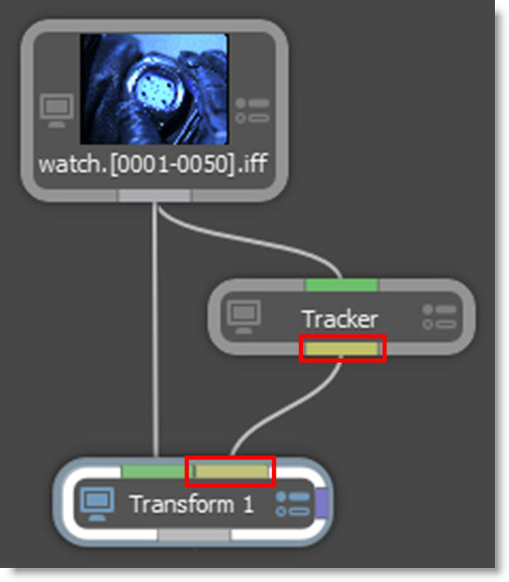
The Data ports are colored yellow.
4 Single-click in the center of the Tracker node to view and edit it.
5 Track an object and apply the tracker to a layer.
6 Single-click in the center of the Transform node to view and edit it.
7 Select a point tracker or tracked layer from the Transform > Transform pop-up menu.
8 Choose Stabilize in the Transform > Mode pop-up menu.
The tracking data from the selected layer is applied to the image and it is stabilized.
9 If you’d like, you can now add various elements to the stabilized image.
10 To reapply the clip’s original motion, copy the original Transform node used to stabilize the image, paste it after the added elements, and hook the Tracker node’s Data output into the new Transform node’s Data input.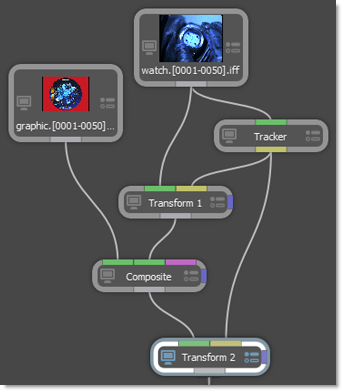
11 Change the new Transform node’s Transform > Mode from Stabilize to Match Move.
The image now has the original motion applied to it. Images can also be match moved without being previously stabilized.
Match Move
1 In the Trees window, drag a Tracker node from the Nodes > Transform group onto the source node you want to track.
2 Add a Transform node from the Nodes > Transform group and connect it to the source node you want to match move.
3 Connect the Trackers Data output into the Transform node’s Data input located at the top right of the node.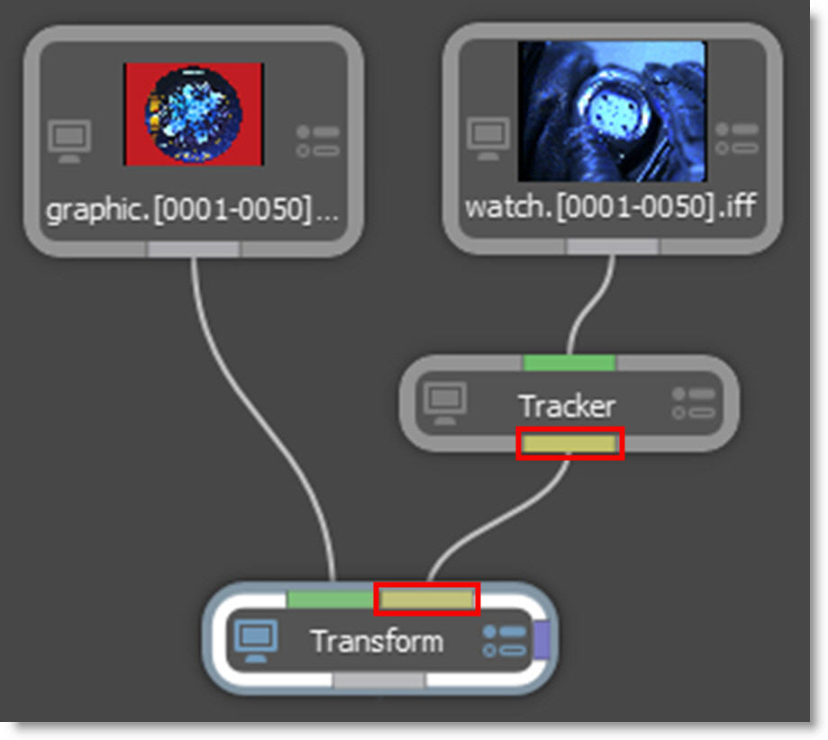
4 Single-click in the center of the Tracker node to view and edit it.
5 Track an object and apply the tracker to a layer.
6 Single-click in the center of the Transform node to view and edit it.
7 Select a point tracker or tracked layer from the Transform > Transform pop-up menu.
8 Choose Match Move in the Transform > Mode pop-up menu.
The tracking data from the selected layer is applied to the image and it is match moved.
9 If necessary, you can use the Transform node’s parameters in conjunction with the tracking transform.
Inserts
Inserts are achieved using the Transform node. When the Data output of a Roto, Tracker or Mocha Pro node is plugged into the Transform node’s Data input, the Layer > Surface corner points are used to set the insert corner-pin.
1 In the Trees window, add a Transform node from the Nodes > Transform group and connect it to the source node.
2 Drag a Tracker node from the Nodes > Transform group onto the source node.
A new branch is created.
3 Connect the Tracker’s Data output into the Transform node’s Data input located at the top right of the node.
4 Single-click in the center of the Tracker node to view and edit it.
5 Track an object and apply the tracker to a layer.
6 Select the Transform node and then the Viewer > Surface icon.
The Surface icon displays the selected layer’s surface when in Transform mode. By default, the Surface is set to the corners of the layer.
7 Adjust the Surface corner points with the on-screen controls to match where the insert should be placed.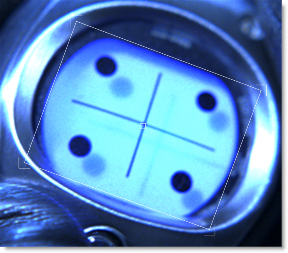
Note: The color of the Surface on-screen controls are blue by default.
8 Single-click in the center of the Transform node to view and edit it.
9 Select Insert in the Transform > Surface pop-up menu.
10 Select the tracked layer from the Surface > Transform pop-up menu.
The Layer > Surface corner points are used to set the insert corner-pin.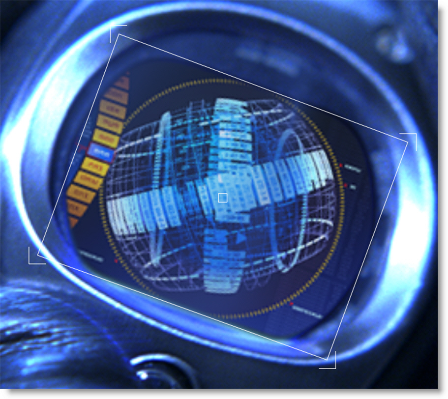
Point Control Tracking With Data Ports
Point control parameters can be match moved. This is achieved by plugging the Data output of a Roto or Tracker node into another node’s Data input. When either a point tracker or tracked layer is selected in the Transform pop-up menu to the right of the point control, the parameter is match moved.
1 In the Trees window, add a node that contains a Data input, for instance, Light > Lens Flare.
2 Drag a Tracker node from the Nodes > Transform group onto the source node.
A new branch is created.
3 Connect the Tracker’s Data output into the Lens Flare node’s Data input located at the top right of the node.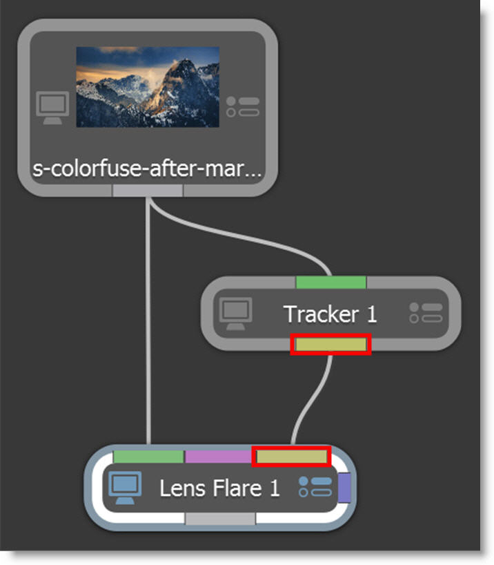
The Data ports are colored yellow.
4 Single-click in the center of the Tracker node to view and edit it.
5 Track an object and apply the tracker to a layer.
6 Single-click in the center of the Lens Flare node to view and edit it.
7 Select a point tracker or tracked layer from the Transform pop-up menu to the right of the Flare > Position parameter.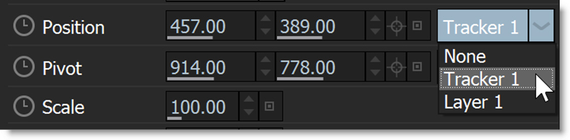
8 Drag through the sequence.
The Position parameter is now match moved to the selected point tracker or tracked layer.
Importing and Exporting Tracking Data
Exporting Tracking Data
Trackers can be exported to the After Effects, Autodesk, Nuke and Shake tracker formats. In addition, the tracking data applied to a layer, either by point trackers or planar trackers, can be exported as a four point corner-pin track.
Note: Mocha tracking data can not be exported as external trackers.
Exporting One to Two Trackers
1 Choose the Tracker (Shift-T) in the Roto Toolbar.
2 Click on the Point tab.
3 Select the trackers that you want to export.
4 Choose Export in the Tracker tab and select the tracker format.
5 When the window pops-up, type in a name and click Save.
Currently, you can export to the After Effects, Autodesk, Nuke and Shake tracker formats.
Exporting Four Trackers for Corner-Pinning
1 Choose the Tracker (Shift-T) in the Roto Toolbar.
2 Click on the Point tab.
3 Using the Shift key, select the four trackers that you want to export in a Z pattern: Upper Left, Upper Right, Lower Left and Lower Right.
4 Choose Export in the Tracker tab and select the tracker format.
5 When the window pops-up, type in a name and click Save.
Exporting a Layer as a Four Point Corner-Pin
1 Select the layer that you want to export.
2 Press the Tracker (Shift-T) in the Toolbar, Choose Export in the Tracker tab and select the tracker format.
3 When the window pops-up, type in a name and click Save.
Note: When exporting a four point corner-pin track to Autodesk products, it is better to use four trackers instead of the tracking information from a layer.
Export Surface Corner Points As Trackers
Layers can optionally have Surface corner points set which can then be converted to Point trackers for export.
1 Select a tracked layer.
2 Click Transform mode and then the Viewer > Surface icon.
The Surface icon displays the selected layer’s surface when in Transform mode. By default, the Surface is set to the corners of the layer.
3 Drag the Surface corners to the desired locations.
4 Select the Tracker (Shift-T) in the Roto Toolbar.
5 Choose the Point Tracker tab.
6 Right-click in the Viewer and select Create Corner Trackers from Layer Surface.
Four point trackers appear on the layer’s surface corners.
7 Proceed to export the four trackers as outlined in Exporting Four Trackers for Corner-Pinning.
Importing Tracking Data
Mocha Pro, After Effects Corner-Pin, Nuke 8 and above, Shake or Simple Format formatted trackers can be imported into Silhouette. If you would like to import trackers from non-supported applications, simply export a Silhouette tracker in Simple Format to see how it should be formatted.
Silhouette
Import Menu
1 Select the Tracker (Shift-T) in the Roto Toolbar.
2 Choose Import in the Tracker tab.
3 Select the Mocha Pro, After Effects Corner Pin, Nuke, Shake or Simple Format tracker file that you would like to import and click Open.
If you select multiple trackers in the import dialog, more than one tracker can be imported at a time.
Note: With some formats, the imported trackers may not line up with the tracked feature. If so, use MultiFrame mode to move the tracker and it’s keyframes into the proper location.
Mocha Pro
1 If you used Copy to Clipboard when exporting to Silhouette Corner Pin in Mocha Pro, you can paste the trackers into a Silhouette Roto node.
2 Mocha tracked layers can also be brought into Silhouette using the Mocha Pro node’s Action menu. This menu creates a Tracker node from the Mocha Pro project without having to go into the Mocha UI.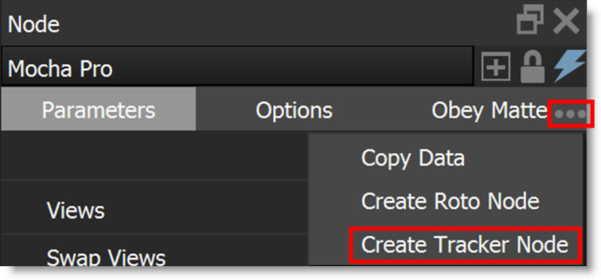
After Effects
1 Double-click on the tracker text file that you exported from Silhouette.
The value of the Comp Pixel Aspect Ratio line at the top of the exported tracker file must match the Pixel Aspect Ratio in the After Effects Composition settings. Edit the exported tracker file as needed.
2 Press Ctrl/Cmd-A to select all and Ctrl/Cmd-C to copy.
3 In After Effects, select a layer in the Timeline and press Ctrl/Cmd-V to paste the Tracker Data.
Note: If you exported a limited work range in Silhouette, go to the start frame of the work range in After Effects before pasting.
4 Open the Window > Tracker controls.
5 In the Motion Source pop-up, select the layer where you pasted the tracking data.
6 From the Current Tracker pop-up, select the Tracker that you just pasted. If you only have one tracker, this would be Tracker 1.
7 Change the Track Type from Raw to one of the available options.
8 Click Edit Target and choose the layer that you would like to apply the motion to.
9 Hit Apply.
Flint / Flame / Inferno
1 Select the Stabilizer.
2 Click on the Imp button below the Track fields and select the tracker file that you saved from Silhouette.
Note: When importing a four point corner-pin track in Flint, Flame and Inferno, it is better to use four trackers instead of the tracking information from a layer.
Nuke
1 Choose File > Import Script and select the tracker file that you saved from Silhouette.
Shake
1 Add a Tracker, Match Move or Stabilize node.
2 In the Tracker node, click the Load button in the Parameter tab and select the tracker file that you saved from Silhouette.
3 For the Match Move and Stabilize nodes, right-click on one of the trackName's in the Parameter tab and choose Load Track File.
4 Select the tracker file that you saved from Silhouette.