Tutorials
Getting Started
Starting the Silhouette Standalone
1 Start Silhouette on Windows systems by selecting Programs > Boris FX Silhouette 2024.5 > Silhouette 2024.5 in the Windows Start menu.
or
2 Start Silhouette on Macintosh systems by going to the /Applications/BorisFX/Silhouette 2024.5 folder and double-clicking on Silhouette.
or
3 Start Silhouette on Linux systems by opening a Terminal window, navigating to the Silhouette install folder and type: ./run.sh
Applying the Silhouette Plug-in
1 Start your host application and apply Silhouette:
• After Effects: Apply Silhouette to a clip in the timeline from the Effects > Boris FX Silhouette menu.
• Premiere Pro: Apply Silhouette to a clip in the timeline from the Effects > Video Effects > Boris FX Silhouette group.
• OFX: The method for applying an OFX plug-in varies. Consult the OFX host software documentation for details.
2 To use Optional Source inputs in After Effects/Premiere Pro: Select the layers using the Optional Sources > Source 1-8 pop-up menus.
3 To use Optional Source inputs in OFX: For node based hosts, connect optional sources to the Source 1-2 inputs. For layer based hosts, select the layers using the Optional Sources > Source 1-2 pop-up menus.
• Resolve: In the Color tab, right-click the source node Silhouette was applied to and select Add OFX Input, drag and drop the optional source from the Media Pool to the Color tab, and connect the green output port of the optional source to the green input of the source node.
4 If you want to preserve the source alpha, change the Source Alpha parameter to Preserve Alpha.
Note: By default, the source alpha is cleared. This is so you can use roto shapes to assist in painting.
Projects
Standalone
When started, Silhouette opens a new, unsaved project. A project contains footage and sessions while a session is a workspace where you composite, rotoscope and paint.
It is recommended that the project is saved before work commences.
1 Select File > Save Project.
The Save Project dialog box opens.
2 Enter a project name, choose a folder and then click Save Project.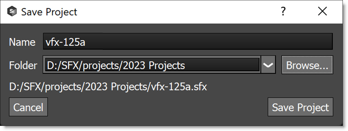
When the new project is saved, a folder is generated using the name of the project and contains the project file, paint data, autosave, and backups.
Plug-in
1 Open the Silhouette user interface.
• After Effects/Premiere Pro: Click the Silhouette Interface > Open button.
• OFX: Click the Open Silhouette Interface button.
The New Project window opens.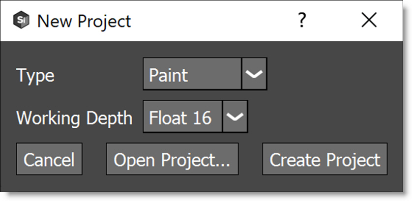
2 When prompted, select a project Type and Working Depth. Normally, it is best to practice to match the host application’s bit depth.
Project Types
• Composite: Automatically adds an Output node to the source and selects the Composite workspace. Back in the host, the Render parameter is automatically set to Output: Composite. Use Output: Cutout if you want RGBA output from Silhouette.
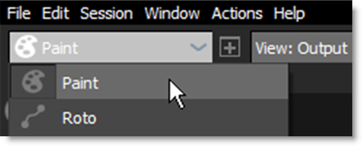
• Paint: Automatically adds Roto, Paint and Output nodes to the source, connects the Roto > Data output to the Paint > Data input and selects the Streamlined workspace. Back in the host, the Render parameter is automatically set to Paint.
• Roto: Automatically adds Roto and Output nodes to the source and selects the Streamlined workspace. Back in the host, the Render parameter is automatically set to Roto.
3 Click Create Project.
The Silhouette user interface opens once the project is created and is stored within the host application’s project data. However, some nodes (Paint and Stability) store sidecar files with the project data, and using these nodes will prompt saving the project file to a folder in the same fashion as the standalone.
Importing and Replacing Media
Before you can start using Silhouette, media (footage) has to be imported. The Silhouette plug-in automatically imports the media (footage) selected in the host application and appears in the Sources window. Although the plug-in is limited to three sources on the host side, you can import an unlimited amount of media directly in Silhouette.
Importing Media
1 Drag and drop files or folders into the Sources window to automatically create sources.
The clip is imported into Silhouette and appears in the Sources window.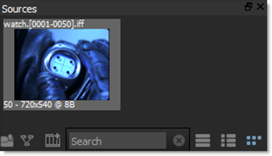
2 Alternatively, import using the file browser using one of these methods:
• Select File > Import > Media.
• Double-click on an open space in the Sources window.
• Click the Import icon at the bottom left of the Sources window.
3 When the File Browser opens, navigate to the location of your clip.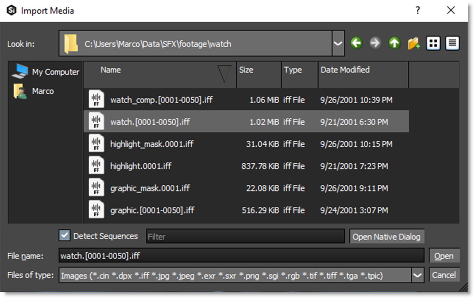
Silhouette supports both image and movie file formats.
Image File Formats
• Cineon (.cin)
• DPX (.dpx)
• IFF (.iff)
• JPEG (.jpg .jpeg)
• OpenEXR (.exr .sxr)
• PNG (.png)
• SGI/RGB (.sgi .rgb)
• TIFF (.tif .tiff)
• TARGA (.tga .tpic)
Movie Clip Formats
Movie file formats are supported through GStreamer which is a versatile media handling library for reading various codecs and footage containers.
• AVI MOVIE files (.avi)
• DV STREAM files (.dv)
• M2TS MOVIE files (.m2ts .mts)
• MKV MOVIE files (.mkv)
• MPEG MOVIE files (.mpg .m2v)
• MPEG-4 MOVIE files (.mp4 .m4v)
• MXF MOVIE files (.mxf)
• QUICKTIME MOVIE files (.mov .qt)
• RED R3D MOVIE files (.r3d)
• WMV MOVIE files (.wmv)
Note: Some clip formats such as MXF will use codecs that Silhouette does not support. In this case, you may need to convert the clip to a supported format.
1 Select a sequence and click Open.
The clip is imported into Silhouette and appears in the Sources window.
Replacing Media
1 In the Sources window, click on a clip to select it.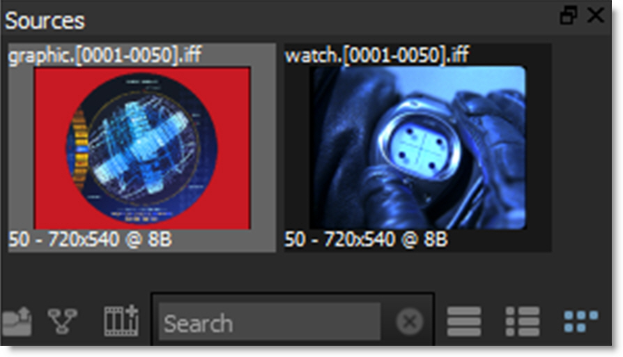
2 In the Object window, click the Browse icon at the far right of the File field.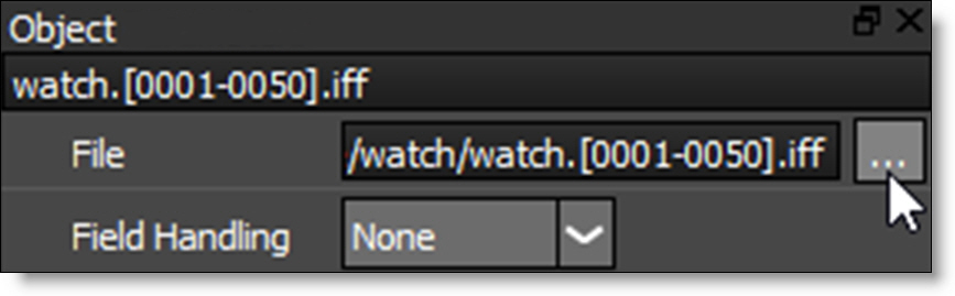
The File Browser opens.
3 Navigate to your clip, select it and hit the Open button.
The old clip is replaced with the new clip.
Managing Media Paths
You can virtualize media paths in order to improve asset sharing between users, asset management and render servers by specifying the file path with a SFX_MEDIA environment variable.
Note: This is accomplished through a default SfxContentResolver that maps a “sfx” scheme to the SFX_MEDIA environment variable, and vice versa.
1 Using the standard method for setting an environment variable on your OS, create an environment variable named SFX_MEDIA with a value being the path where you media is stored, for instance, C:\Media\footage\.
2 Import a clip that is nested under the path you set for the environment variable.
3 Select the imported clip in the Sources window.
Please note that in the Object window > File field, the beginning of the source’s path is now sfx://.
4 Go to another computer with the same media, but a different folder structure, and set the SFX_Media to the new path.
5 Open the project created by the first machine and all of the source footage will be linked properly on your second machine.
Creating Sessions
Sessions are where you composite, rotoscope or paint and are required before you can start working in Silhouette. Think of sessions as sub-projects where there can be multiple sessions within the project.
When the project is created in the Silhouette plug-in, a session is automatically created based on the project type, but additional sessions can also be added.
Session Templates
Templates are presets for automatically adding nodes to the session and selecting a workspace.
1 Load some source footage.
2 Highlight the clip in the Sources window.
3 Choose Session > New Session, press Ctrl/Cmd-N or click the New Session icon at the bottom of the Sources window.
or
4 Drag the clip thumbnail from the Sources window to the Trees window.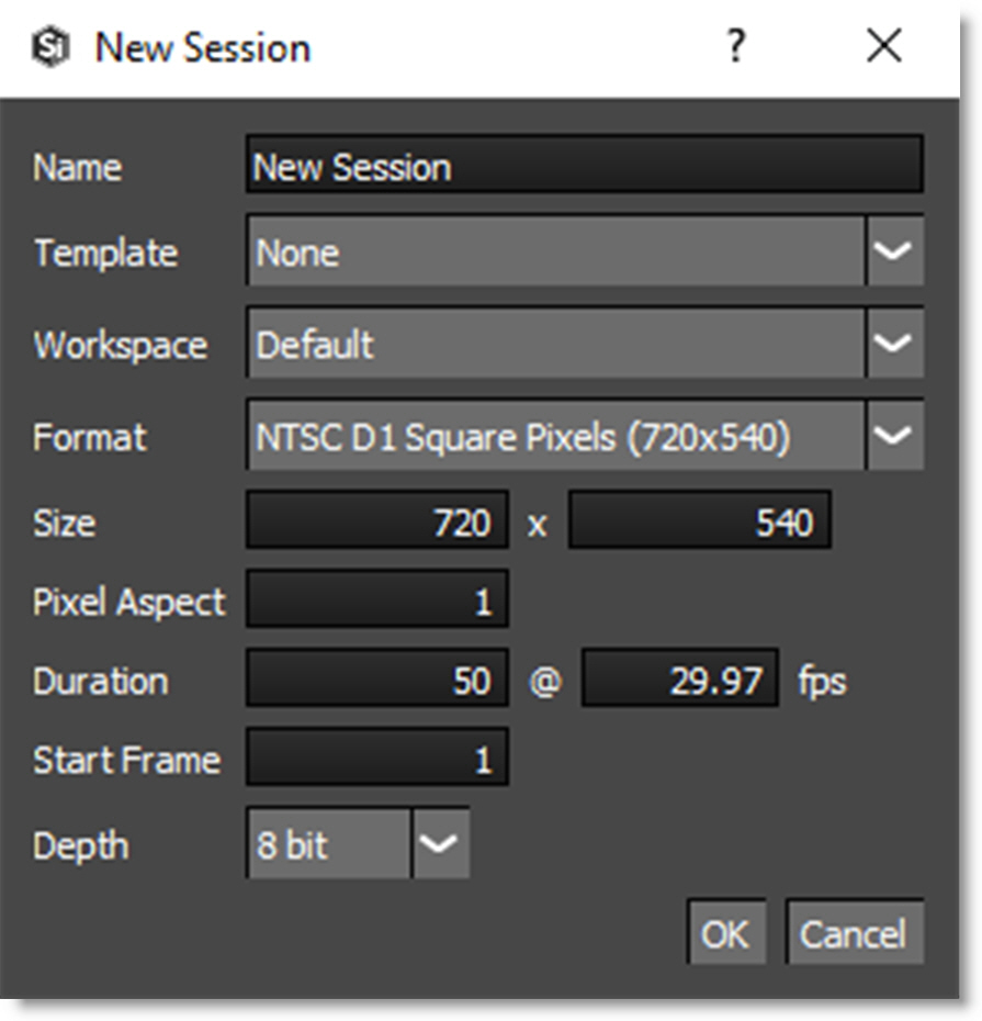
The clip settings are automatically imported into the session settings.
Note: If an in and out point has been marked for a source clip, the marked duration will be used for the session duration. For more information on source clip in and out points, see Source In and Out Points.
5 Select the Roto template.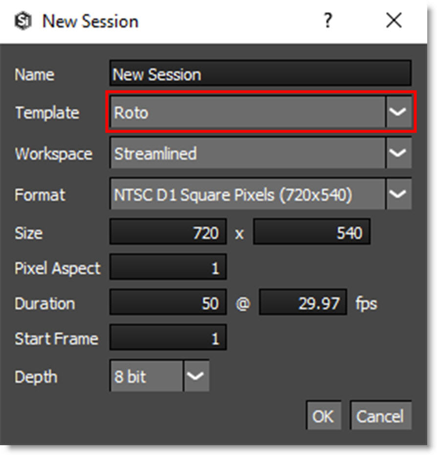
You can choose from the following templates:
• Composite: Automatically adds an Output node to the Source and selects the Composite workspace.
• Paint: Automatically adds Roto, Paint and Output nodes to the Source, connects the Roto > Data output to the Paint > Data input and selects the Streamlined workspace.
• Roto: Automatically adds Roto and Output nodes to the Source and selects the Streamlined workspace.
6 If you’d like, rename the session in the Name field and click OK.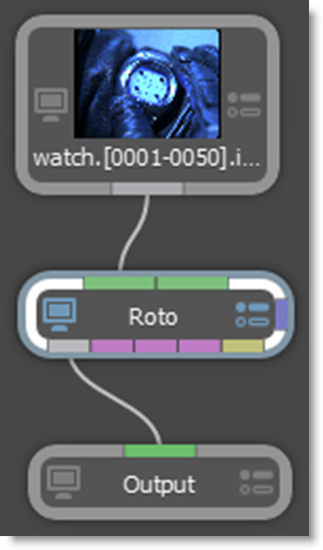
The source node is automatically connected to Roto and Output nodes. The Output node determines the file format, file name, disk storage location, and channels to be rendered. In addition, the Streamlined workspace is selected. Optimized for Roto and Paint projects, the Streamlined workspace reduces the size of the Trees window to make room for the Object List and Paint History immediately below.
Editing Sessions
Once you have created a session, you can change its settings at any time by using one of the two methods listed below.
1 From the pull-down menu at the top of the screen, select Session > Session Settings.
or
2 Press Ctrl/Cmd-Shift-S.
In either case, the session window opens and you can change the settings. When the Edit Session window opens, make the desired changes.
Shifting a Source Node in Time
You can shift a Source node in time. This is useful for lining up frames that are numbered differently.
1 Single-click on the Source node in the Trees window to view and edit it.
Once active, the Source node’s parameters appear in the Node parameters.
2 Drag the Time Shift numeric field to the desired frame or enter a value by clicking on the number.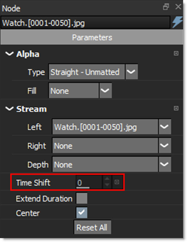
The start frame for the node is adjusted by the Time Shift value.
Playback and Caching
Enhance playback performance using the RAM cache, caching to a local disk or the Cache node.
Cache Frames To RAM
1 Play the sequence to cache it into RAM.
After playing through once, it will then play in real-time if enough RAM is available. At the bottom right corner of the interface, there is a numeric readout (Cache Display). It displays the percent of system RAM and GPU memory used as well as the session’s bit depth.
If the duration is longer than the maximum frames that can be cached into RAM, the sequence will not play in real-time.
2 Change the Timebar > First Frame and Last Frame to a duration less than the maximum number of frames in the Cache Display so that you can achieve real-time playback.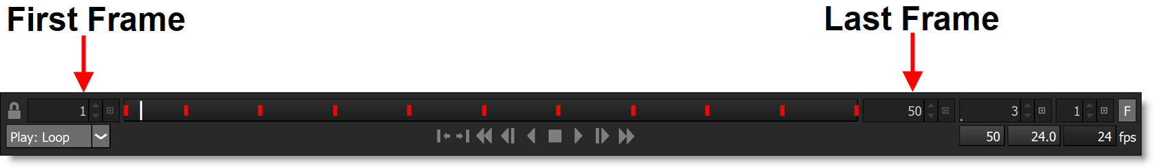 Play the sequence after the new, shorter duration has been set.
Play the sequence after the new, shorter duration has been set.Once the sequence is played through once, it will then play in real-time.
Preload Frames To RAM
Source frames can also be automatically cached in a background thread. The amount of preloaded frames is controlled by a Cache > Preload Frames preference with the default value being 10 frames.
1 Select File > Preferences on Windows and Linux or Silhouette > Preferences on Macintosh.
2 Go to the Cache group.
3 If you’d like, you can change Preload Frames to a higher value.
4 Click Apply.
Increase Amount of Frames During Playback
There are number of ways to increase the amount of frames that can be played back in real time.
1 Enable the Viewer > ROI (Region of Interest) to work on a sub-region of the image.
2 Select File > Preferences on Windows and Linux or Silhouette > Preferences on Mac and increase the %Total Physical RAM parameter in the Cache preferences (requires a restart of Silhouette to take effect). Please note that setting the % Total Physical RAM too high could cause instability if running other memory intensive programs.
3 In the Roto node, change the View from Output to Foreground.
4 Shorten the length of the clip by adjusting the First and Last Frame in the Timebar.
5 Change the proxy setting to 2:1, 3:1 or 4:1.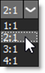
6 If you are working with high resolution files in a non-Paint Float session, change the session depth to 8 bits while you work, then switch back to Float for rendering.
Note: When painting, do not use a proxy setting other than 1:1 and make sure that you remain at the session’s original bit depth. Otherwise, the cursor changes to a prohibition icon (circle-backslash).
Cache Node
Caches the result of all upstream nodes to disk, alleviates the need to reprocess that section of the Tree and loads as fast as a source file.
Source Caching To Disk
Media from a slow network drive is automatically copied to a fast local drive once you specify the source and storage locations in the Cache > Local Cache preferences. Then, when you load a sequence from the slow network drive, the source node will see that it’s in the source path and copy it to the fast storage path. The next time the media is requested from the network drive, it will read it from the local cache instead.
Viewer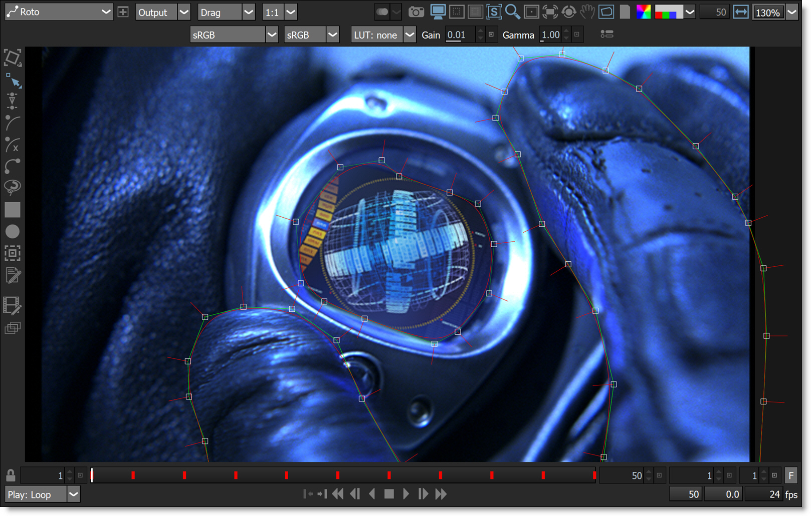
Color Management
Silhouette uses the OpenColorIO standard originally developed by Sony Pictures Imageworks for its color management. You can load custom color configuration files and custom LUTs, apply colorspace conversions, as well as use other controls for fine tuning.
1 Make sure that the Display Options icon is enabled in the Viewer.
Silhouette automatically tries to determine the colorspace based on the data in the file and other information from the header.
2 If not set correctly, change the input colorspace of the current scene using the Colorspace pop-up menu.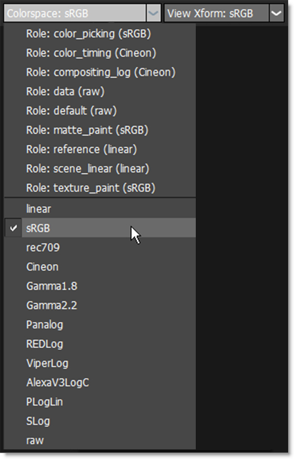
When using Cineon/DPX images with the Color Management > Cineon/DPX Working Space preference set to Linear, the input colorspace should be set to Linear. When the preference is set to Log, the Cineon colorspace should be used.
3 If you are using a custom OCIO configuration with multiple Display options, choose the colorspace of the display using the Display pop-up menu.
Note: If there is only one Display option, the Display pop-up menu is hidden.
Use View Transform to set the transform that occurs between the input scene’s colorspace and the display colorspace.
4 Select a colorspace that matches your display device using the View Transform pop-up menu.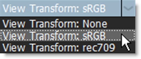
5 To adjust the brightness of the image in the Viewer, use the Viewer > Display > Gain and Gamma settings.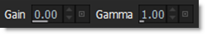
You can select a custom OpenColorIO (.ocio) configuration file by choosing it in the Color Management > OCIO Configuration preference.
For more information on OpenColorIO, including the OCIO file format, please visit http://opencolorio.org/.
Viewing Channels In The Viewer
1 Click on the Red, Green, Blue or Alpha buttons to solo that channel as a gray scale image.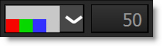
If only one component is selected, it is displayed in gray scale. The horizontal white bar above the RGBA buttons quickly toggles the display of the image back to full color mode.
2 Select the horizontal white bar above the RGBA buttons to quickly toggle the display of the image back to full color mode.
3 Either press the Alpha button (to the right of the blue button) or the A key to cycle the state of the alpha display.
Note: To view a shape’s alpha channel, you must first set the View to Output before pressing the Alpha button or A key.
Hitting the Alpha button or A key once superimposes the alpha channel over the image. Pressing a second time displays the alpha channel over black. Hitting again shows only the color image.
Shift-A activates RGBA mode which does the following: Toggles the View to Output, superimposes the alpha channel over the image and deactivates the Overlay. Pressing Shift-A again returns the Viewer to its previous state.
Viewer Navigation
Zooming
1 Select a value between 25% and 500% in the Zoom pop-up menu.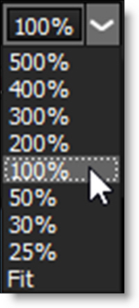
or
2 Use the scroll wheel on your mouse to zoom in and out of the image.
or
3 Press Space Bar-Shift and move the mouse up to zoom in or down to zoom out.
or
4 Use the + or = keys to zoom in and the - key to zoom out.
Zoom and Centering Presets
1 Press the F keyboard shortcut or select Fit from the zoom pop-up window to display the image as large as possible within the Viewer window.
2 Press the H keyboard shortcut or double-click the middle mouse button to set the image to a 100% zoom level and center it in the Viewer.
3 Press Ctrl/Cmd-F to center the selected object in the Viewer.
Viewer Rotation
Rotating the Viewer can facilitate rotoscoping and painting.
1 Select the Rotate icon to enable Viewer rotation mode.
Once Rotate is enabled, the Adjust Rotation editing control (hand icon) becomes available.
2 Press the Adjust Rotation icon to enable it.
3 Click and drag in the Viewer to set the angle.
Once the angle has been set, you will need to disable Adjust Rotation to use the node’s tools.
4 Select the Adjust Rotation icon again to disable it.
Opening Additional Viewers
Open additional Viewers that can be set to any node or view.
1 At the top left of the Viewer, click the New Viewer icon.
A new viewer opens as a floating window.
2 Select the node to view.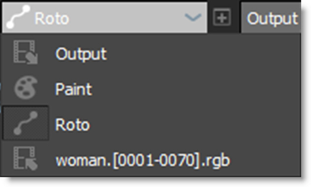
The new Viewer has the following controls: Node, View, Update Mode, Stereo View, OCIO, Preview, Channels, and Zoom controls. The remainder of the controls are shared with the main Viewer.
Note: Multiple viewers from the same node have the option of being synchronized in terms of zoom and pan using the Use Viewer > Synchronize Viewers preference.
ROI (Region of Interest)
ROI (Region of Interest) crops the image in the Viewer to a user defined size and can be animated. This is especially useful when you only need to work within a smaller region of a larger image as it will use less memory and process faster. If expanded, the ROI will display overscan pixels which can then be manipulated.
Smaller ROI for Performance
The ROI can be made smaller than the session size to speed up processing and save memory. This is especially useful when working with larger images.
1 Load some source footage and create a session.
2 Single-click in the center of the source node in the Trees window to view and edit it.
3 Display the ROI controls by clicking the ROI icon above the Viewer.
Once the ROI icon is activated, the ROI controls appear above the Viewer.
4 Make sure the Enable button is active.
5 Drag one of the corner points to size the ROI.
Note: You can also Ctrl/Cmd-Shift-drag a square region in the Viewer to draw a ROI region.
6 Move the ROI by clicking and dragging its bounding box.
7 Animate the ROI by enabling the Animate icon and adjust the ROI at various frames.
8 To avoid moving the ROI by mistake after it has been set, disable the Viewer > ROI icon.
This hides the ROI controls, but it is still active.
Note: To temporarily turn off the ROI effect, toggle the Enable icon.
9 To render the ROI, make sure that Render ROI is enabled in the Render Options.
ROI to Reveal Overscan Pixels
If the source’s DOD (Domain of Definition) is larger than the session, the ROI can expand to reveal overscan pixels which can then be manipulated.
1 Load some source footage whose DOD is larger than the session you are working in.
2 Single-click in the center of the source node in the Trees window to view and edit it.
3 Display the ROI controls by clicking the ROI icon above the Viewer.
Once the ROI icon is activated, the ROI controls appear above the Viewer.
4 Make sure the Enable button is active.
5 Click the Set ROI to DOD icon in the Viewer.
The ROI will automatically be set to match the size of the source’s DOD and will reveal any overscan pixels.
Sequence Editor
Silhouette can perform editing tasks such as cutting, joining, moving, copying, replacing, trimming, retiming and repeating clips in the Sequence Editor. The sequence can then be used as an element in the Trees window.
Creating a Sequence
A sequence is comprised of multiple clips edited together.
1 Select the New Sequence icon in the Sources window.
A sequence object is created in the Sources window and the Sequence Editor appears.
2 Drag and drop clips from the Sources window into the Sequence Editor.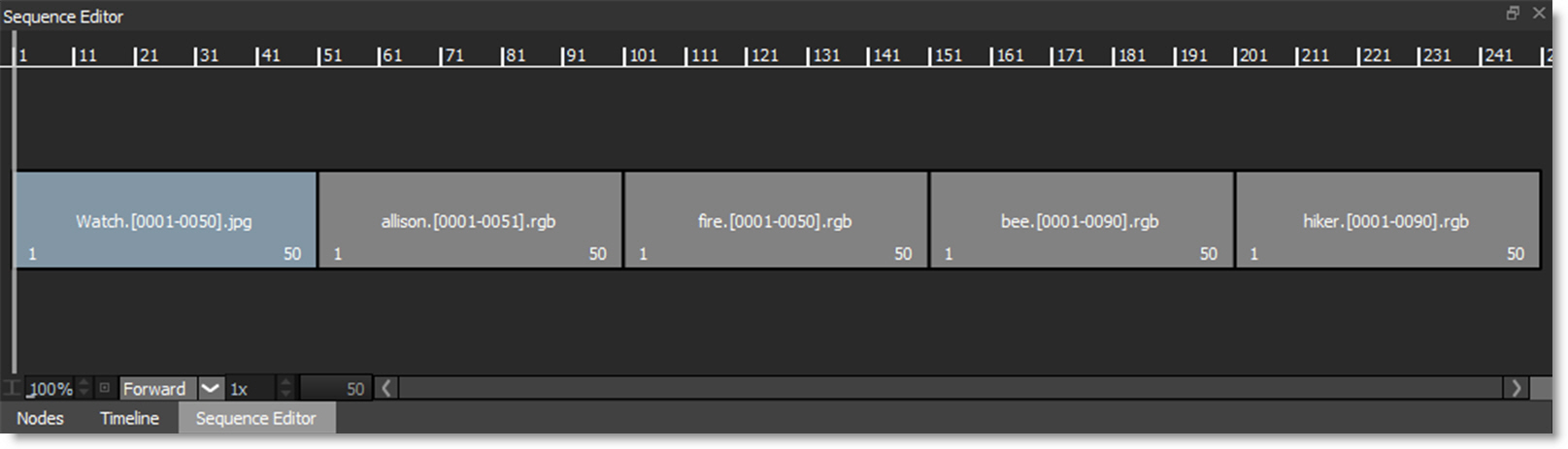
3 Drag and drop to insert clips or Alt-drag and drop to replace clips.
If you select one or more clips in the Sources window before pressing the New Sequence icon, the clips are assembled in selection order using in and out points, if they are set, into a new sequence.
4 Drag and drop the sequence from the Sources window into the Trees window.
The sequence can now be used as an element in the Trees window just like any other source.
Marking In and Out Points
Clips in the Sources window can have in and out points which are used when creating a sequence. In and out points are also useful within the sequence to define a region to be moved, copied, replaced or deleted.
1 Double-click on a clip in the Sources window.
The clip is loaded into the Viewer and Mark IN and Mark OUT icons appear.
2 Set the Timebar to the in point.
3 Click the Mark IN icon or press the I key.
4 Set the Timebar to the out point.
5 Click the Mark OUT icon or press the O key.
When setting in and out points for a clip, the clip takes over the Viewer. To return the Viewer to a sequence or a node, double-click the sequence in the Sources window or a node in the Trees window.
Moving, Copying, Replacing and Deleting
The highlighted selection can be moved, copied, replaced or deleted.
Moving
1 Click on a clip or drag select multiple clips to select them.
2 Click somewhere in the highlighted region and drag and drop to a new location.
The selection is moved.
Copying
1 Click on a clip or drag select multiple clips to select them.
2 Click somewhere in the highlighted region and Shift-drag and drop to a new location.
The selection is copied.
Replacing
1 Click on a clip or drag select multiple clips to select them.
2 Click somewhere in the highlighted region and Alt-drag and drop on either a destination clip or a marked region.
The destination clip or marked region is replaced.
Deleting
1 Click on a clip or drag select multiple clips to select them.
or
2 Mark IN and Mark OUT points in the Sequence Editor.
3 Press the Delete key.
The selection is deleted.
Trimming
The head and tail of a clip can be lengthened or shortened using the Trim controls.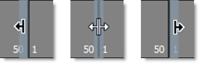
Clicking on a cut enables trimming and displays both sides of the cut in the Viewer.
1 Click and drag in the center of a cut between two clips (double-arrow cursor appears) and both sides of the cut are trimmed.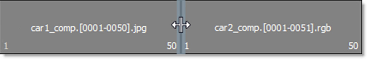
2 Click and drag to the left of the cut (left arrow cursor appears) and the outgoing clip is trimmed.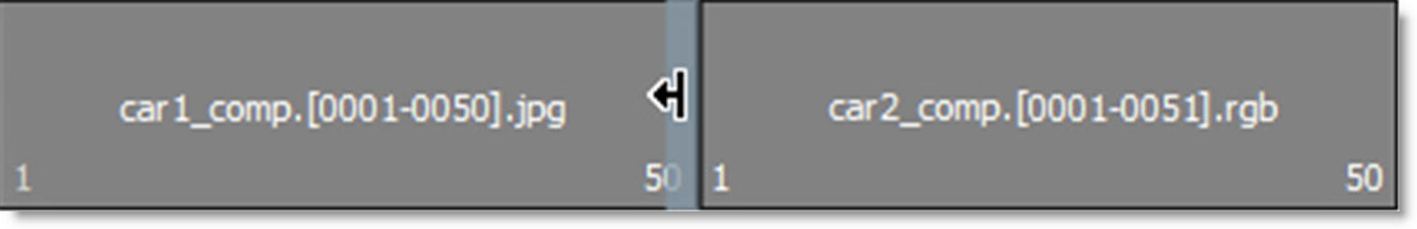
3 Click and drag to the right of the cut (right arrow cursor appears) and the incoming clip is trimmed.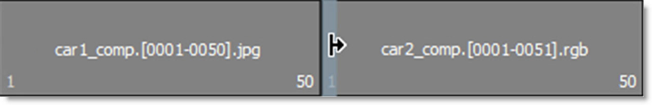
Note: After selecting the left, right or center of a cut, the left and right arrow keys can be used to trim frames one at a time.
Change Speed and Direction
Modification of the speed and direction of selected clips is possible in the Sequence Editor.
Changing Speed
1 Click on a clip or drag select multiple clips to select them.
The Segment Speed field controls the speed of selected clips and displays as a percentage. A value of 50 slows down by 50%, a value of 100 does nothing, and a value of 200 is twice as fast.
2 Using the Segment Speed field, enter a value of 200 to double the speed.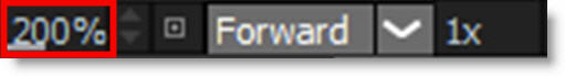
3 Enter a value of 50 to slow the clip down by half.
Note how the duration field has doubled in duration.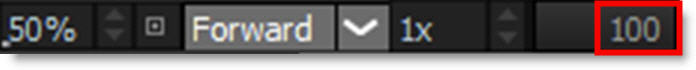
Reversing Direction
1 Click on a clip or drag select multiple clips to select them.
2 Change the playback mode to Reverse in the Segment Direction field.
The order of the frames is reversed.
Looping A Clip
1 Click on a clip or drag select multiple clips to select them.
2 At the bottom left of the Sequence Editor, increase the Loop Count value from 1 to 3.
The clip is repeated three times.
3 Select the Segment Direction: Forward, Reverse or Bounce.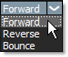
The clip is repeated three times using the selected direction.
Freeze Frame
1 Drag the Timebar to the frame you would like to freeze.
2 Use Add Edit before and after the frame so a single frame clip is created within the Sequence.
Note: The Add Edit icon is located at the bottom left of the Sequence Editor.
3 Zoom the Sequence Editor in using either Middle mouse scroll or Shift-Middle mouse scroll (10x faster) while hovering the cursor over the single frame clip.
Note: Selecting a single frame clip is difficult unless you zoom in because the trim handles will most likely be selected instead.
4 Click on the single frame clip to select it.
5 Enter the freeze frame duration in the Loop Count field, for instance, 10 for 10 frames.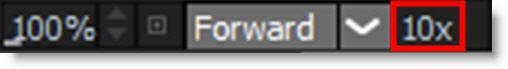
6 Click OK.
The frame is frozen for the specified period.
Silhouette Plug-in - Host Application Tips
Resolve - Working with Alpha
To use the alpha channel created by Silhouette in Resolve, a specific workflow is required.
Edit Tab
1 Apply Silhouette to a clip in the Edit tab.
2 Using Resolve 17 or later, make sure Use Alpha is enabled.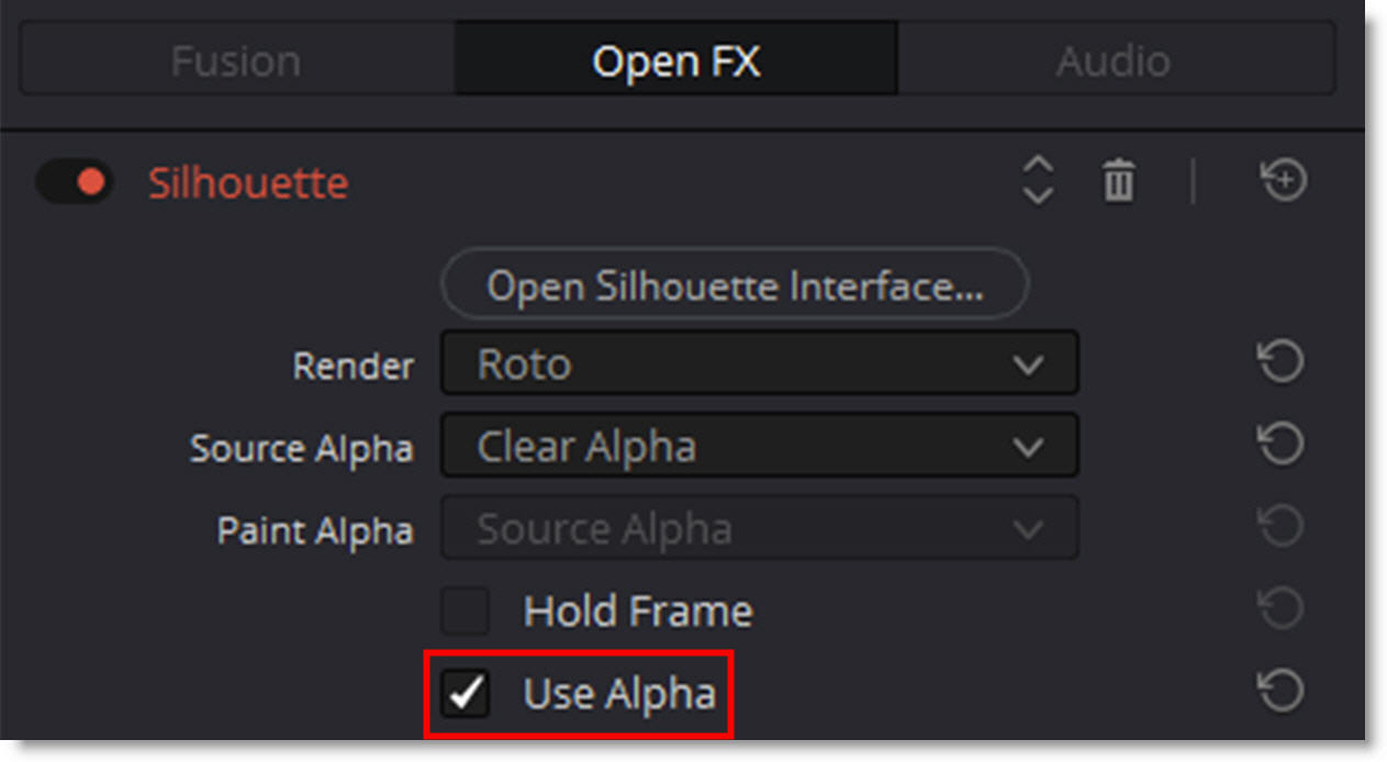
Note: When Silhouette is applied in the Edit tab, only one input can be used. An optional source can only be input into Silhouette through the Resolve > Color tab.
Color Tab
1 In the Color tab, apply Silhouette to the source media's node.
2 Right-click on the node and select Use OFX Alpha.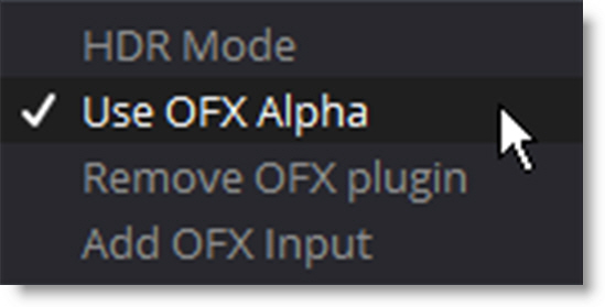
3 Right-click an empty area of the Node Editor and choose Add Alpha Output to reveal the Node Tree output on the right.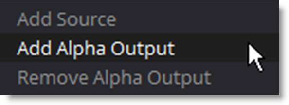
4 Connect the node's key output to the Alpha output at the right of the node editor.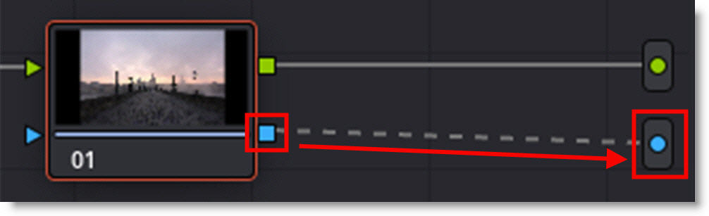
Alpha channels created in Silhouette will now be available for use in Resolve.
Multiple Resolutions In Nuke
When using optional sources that are a different size than Silhouette’s primary input, you will need to add Reformat nodes to the optional sources.
1 In Nuke, add Reformat nodes to the sources that are a different size than the primary Silhouette input.
2 Set the Reformat node’s Output Format, the Resize Type to None and enable Center.
3 If you want to center the image inside Silhouette, select the source thumbnail in Silhouette’s Trees window and disable Center in the Node window. This defers the centering to the Nuke setting.