SynthEyes
Description
The SynthEyes node provides an environment for automatically tracking a shot in 3D or loading existing scenes in Alembic or FBX formats. Automatic tracking reconstructs a 3D camera and point cloud from an image sequence, allowing added elements to follow the original camera’s perspective and movement.
You can select 3D tracks to define a plane, then place cards and geometric primitives in 3D space. After tracking, you can inspect the tracking error, remove unreliable features and refine the camera solution. The resulting scene can be connected to other 3D nodes for image projection, compositing and rendering.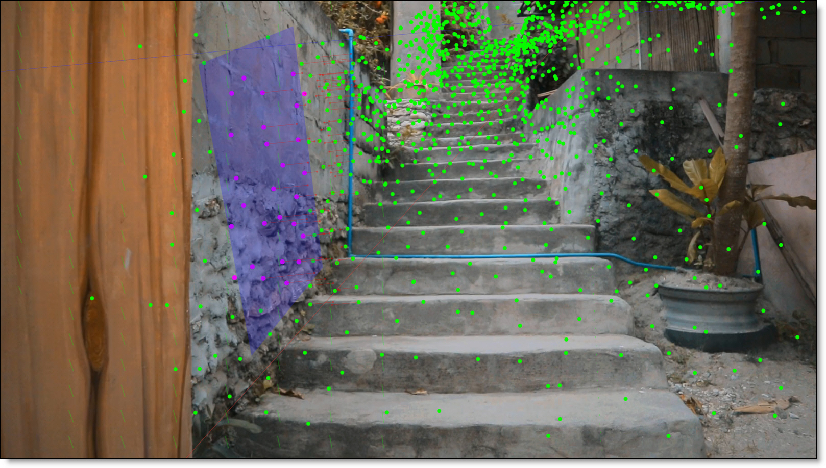
Using the SynthEyes data port, you can:
• 3D Track
• Use cards to Insert, Match Move and Stabilize in the Transform node
• Unproject images, paint or composite them, and then reproject the results
• Transform Paint strokes with cards
• Import cards and convert them to layers for use in Roto and Tracker capable nodes
• Stabilize and Unproject directly in the Viewer using cards
• Convert 3D trackers into 2D point trackers
Go to the SynthEyes tutorials to see how it works.
Node Group
3D.
Tracker
The SynthEyes node features a built-in camera tracking and solving system.
Workflow
SynthEyes works by tracking the scene and deriving the camera’s movement based on the relative motion of tracked features.
Step 1 - Creating A Camera Solve
Before adjusting settings, click the Solve button and review the initial results. For most shots, default settings provide a solid starting point.
Step 2 - Masking Problematic Objects
To prevent obstructions from interfering with the solve, isolate them using a Roto or Matte Assist ML node. Then, connect the output to the Occlusion Matte input and enable the Matte > Use Occlusion Matte parameter to exclude those areas from processing.
Common Items to Mask
• Large moving objects (e.g., actors, cars)
• Clusters of smaller, high-contrast moving objects
• Distant areas like clouds or skylines that don't contribute to the solution
Step 3 - Solve the Shot
Click the Solve button to begin processing.
Solve Process Stages
• Blipping: Identifies auto features (blips) while ignoring masked areas.
• Solving: Generates a camera solution.
Post-Solve Review
• The Viewer displays the solved camera, features, and ground plane grid.
• The Solve Data column presents the average pixel error for the scene.
• Focal length updates based on solver calculations.
A solve with a pixel error below 1.0 is good; if the error is above 1.5, consider parameter adjustments.
Camera
Solve
Start the solve process using the selected parameter settings. Running it again will clear previous results.
Focal Length
Enter the known focal length here. By default, Unknown is checked, disabling the field. After solving, this field updates to the calculated focal length.
Film Back
Defines the camera’s horizontal and vertical film back (also known as sensor size). Adjusting one value automatically updates the others to match the clip’s dimensions.
Reset All
Removes all solved data from the scene and resets all parameters.
3D Motion
Defines the type of movement within the scene, based on SynthEyes conventions.
Motion Type
Normal Motion
The most common camera movement--typically the default starting point.
Crash Pan
Used for rapid panning shots.
Low Detail
Ideal for scenes with minimal trackable detail, such as green screen backgrounds.
Zoom Lens
Enable when the camera uses lens zoom during the shot.
On Tripod
Indicates a stationary tripod-mounted camera, used for PTZ (pan-tilt-zoom) solutions.
Locked Shot
If the camera remains stationary, enable this option. It’s designed to assist in solving motion for objects when there’s no camera movement.
Corners
Recognizes structural features like buildings, windows, and bricks, aiding in non-organic scene solving.
Features
Defines the automatic tracking features.
Min Trackers/Frame
Specifies the number of auto feature trackers to detect per frame.
Max Tracker Count
Sets the maximum number of auto feature trackers across the entire frame range.
Add More Trackers
Adds additional trackers between existing paths to increase point cloud density.
Small Blip Size
Defines the smallest detectable feature size (in pixels).
Large Blip Size
Defines the largest detectable feature size (in pixels).
Occlusion Source
Excludes an area from being tracked.
Source Alpha
Uses the source alpha.
Occlusion Matte
Uses the occlusion matte input.
Invert
Inverts the matte.
Pre-Processing
Images that contain film grain or video noise, lack contrast or sharpness, or exhibit flicker can be tracked more accurately by applying certain filters during the tracking process. Filters such as Blur, Sharpen, Contrast, Gamma, Denoise and Deflicker will increase tracker accuracy for problematic images.
Blur
Applies a blur to the image features.
Sharpen
Sharpens image features.
Contrast
Increases contrast.
Gamma
Increases brightness by modifying only the values between the white and black points, leaving those points unchanged.
Denoise
Applies a denoise algorithm to smooth out noise while retaining detail.
Deflicker
Corrects image flicker or brightness variation over time, which has a habit of interfering with tracker accuracy.
Preview
Shows the effect of the Pre-Processing parameters on the entire image in the Viewer.
Solve Data
Displays solve results.
Solve Output
Opens a dialog displaying messages from the SynthEyes process, providing useful debugging insights for solving issues. Also includes a summary of the Camera Solve.
Average Error
HPIX graph displaying the scene’s average error per frame and overall error. See Average Error below for details.
Clean Up Features
Cleans up a solve after it has been completed.
Bad frames
Disable bad frames in solved features equal to or over the HPIX threshold.
Short-range Trackers
Remove features that were solved from ranges shorter than the set frame number.
High-Error Trackers
Remove any features that have too many bad frames. Based on the percentage of frames that are bad and the upper HPIX of a bad frame.
Fix Features
Clean up the solved features based on the settings above.
Refine Solve
Updates a cleaned-up solution without starting over, providing a quick way to minimize pixel drift.
UV Ref Frame
Defines the reference frame for UV coordinates.
SynthEyes Terminology
The 3D camera solver leverages SynthEyes tracking and solving processes, adopting its terminology to describe key functions, for instance, Features, Blips, and Trackers.
Features
A feature is an individual point of interest tracked in the scene, either in 2D (x, y) or as its 3D (x, y, z) equivalent after solving.
Blips
A blip is SynthEyes' term for a point of interest within a single frame. During auto feature generation, SynthEyes analyzes each frame, identifying and labeling blips based on notable features. Within Silhouette, this process runs invisibly as part of the camera solve, but blip size can be adjusted via parameters.
Trackers
For auto features in SynthEyes, tracking occurs by linking blips that correlate across frames, forming feature trackers.
Adding More Trackers
The Add More Trackers field increases point density between existing trackers. By analyzing the paths of current auto features, more features are placed along those tracks. While adding more trackers can improve solve accuracy, it also extends solve time.
Solve Quality & Average Error
When a solve is complete, a graph appears under Solve Data, displaying the Horizontal Pixel Error (HPIX), which represents the average pixel error across frames.
Evaluating Solve Accuracy—Good vs. Bad Error
Aim for an average error below 1 pixel.
• 1-2 pixels isn't terrible, but a value of 0.9 or lower is considered excellent.
• Higher error values indicate a poor solution.
SynthEyes filters out high-error features during cleanup, which helps improve solve quality. But if a shot fails to solve, it’s often because extreme pixel errors caused too many features to be removed. Try adding more trackers and adjusting the blip size to give the solver more reliable data.
Toolbar
Tracker
The SynthEyes node features a built-in camera tracking and solving system.
Select Points
Selects tracked 3D points to calculate a solved plane to be used as a surface. After a point selection, a purple line appears from each selected point to its closest point on the plane. Longer lines indicate points that fit the plane less accurately.
Card
Adds a card object to the scene which you can use to insert 2D layers or unproject, paint or composite, and then reproject the original motion.
To place a primitive on a tracked surface, select three 3D points with Select Points or choose an existing plane in the Object List, then use the Card tool and click-drag in the Viewer to create the card.
Primitive
Choose from several wireframe 3D primitives to verify the accuracy of your 3D track or to run workflows where you unwrap, paint or composite, and then rewrap the original motion. Available options include Sphere, Hemisphere, Cylinder, Cone, Cube, and Pyramid.
To place a primitive on a tracked surface, select three 3D points on that surface with Select Points or choose an existing plane in the Object List. Press and hold the Primitive button to pick a shape, clicking again to cycle options. Click in the Viewer to set the base, then move the pointer to size the primitive and click to confirm each dimension.
Transform Controls
Transform (T)
Transform the selected object using position, scale and rotation controls.
Position (Q)
Moves the selected object along the x, y or z axis.
Scale (E)
Scales the selected object along the x, y or z axis.
Rotate (W)
Rotates the selected object along the x, y or z axis.
Point of Interest
When you’re looking through the perspective camera, it shows you the camera’s point of interest so you can see exactly where the view is rotating from. This makes it much easier to navigate the scene, since you always know the center of rotation and can orient yourself as you move around.
Controls
Load 3D Scene
Imports Alembic, FBX and USD scene files.
Depending on the selected object, the following parameters are available.
Transform
Position
Moves the selected object along the x, y or z axis.
Scale
Scales the selected object along the x, y or z axis.
Rotate
Rotates the selected object along the x, y or z axis.
Reference Frame
The Reference Frame is used when a transform is requested from the selected object. It ensures that the transform on this frame will be the identity.
Camera
Mode
Determines the camera projection type.
Perspective
Simulates a real-world camera, where objects diminish with distance and parallel lines converge.
Orthographic
Removes perspective, keeping object scale constant regardless of depth for technical and alignment views.
Lens Squeeze Ratio
Adjusts the horizontal scaling of the image to simulate anamorphic lenses. Values other than 1.0 introduce horizontal stretch or compression, useful for matching or correcting anamorphic footage.
Near Clip
Sets the minimum distance from the camera at which geometry is rendered. Objects closer than this distance are not visible.
Far Clip
Sets the maximum distance from the camera at which geometry is rendered. Objects beyond this distance are not visible.
Sensor Fit
Specifies how the sensor is fit to the output image when their aspect ratios differ. This determines whether the horizontal or vertical field of view is preserved, or if the image is scaled to fill the frame.
Vertical Aperture
Defines half of the sensor’s vertical size and influences the vertical field of view in combination with focal length.
Horizontal Aperture
Defines half of the sensor’s horizontal size and controls the horizontal field of view.
Use Session Aspect Ratio
Uses the session’s output aspect ratio--pixel aspect ratio × width ÷ height--for the camera framing. When enabled, the camera’s Aspect Ratio value is ignored.
Aspect Ratio
Sets the camera’s width-to-height framing ratio when Use Session Aspect Ratio is disabled. It changes the camera projection, not the session’s output dimensions, and is independent of the aperture settings.
Focal Length
Controls how wide or narrow the camera’s view is.
Focus Distance
Sets the distance, in scene units, from the camera to its focus plane. It does not change the camera’s perspective or framing but can be used by depth-of-field-aware rendering.
Color
Sets the color of the camera.
Card
Dimensions
Sets the width and height of the card in 3D local units.
Color
Sets the color of the selected object.
Scene Transform
Select Scene Transform in the Object List to adjust the scene’s Position, Rotate, and Scale. You can also click a point in the scene and choose Make Origin to shift the entire scene relative to the world-origin grid, including its camera, and these changes stack with upstream scene transforms. Use the replacement object’s own transform when you want to move only that surface, or use the node’s placement controls when you want to move only its image.
3D Views
Located in the Viewer, there are a number of 3D Views to visualize the 3D point cloud. See the 3D Views options for more information.
3D Scene Export
File > Export > Alembic, FBX or USD exports the solved camera, tracked 3D points, and scene geometry for use in another application. Object transforms and camera animation are sampled over the Timebar work area using the session’s frame rate and starting frame.