Compositing
Compositing and Multiple Nodes
1 Import some footage conducive to compositing, for instance, a foreground RGBA and a background clip.
2 Highlight the foreground RGBA clip in the Sources window.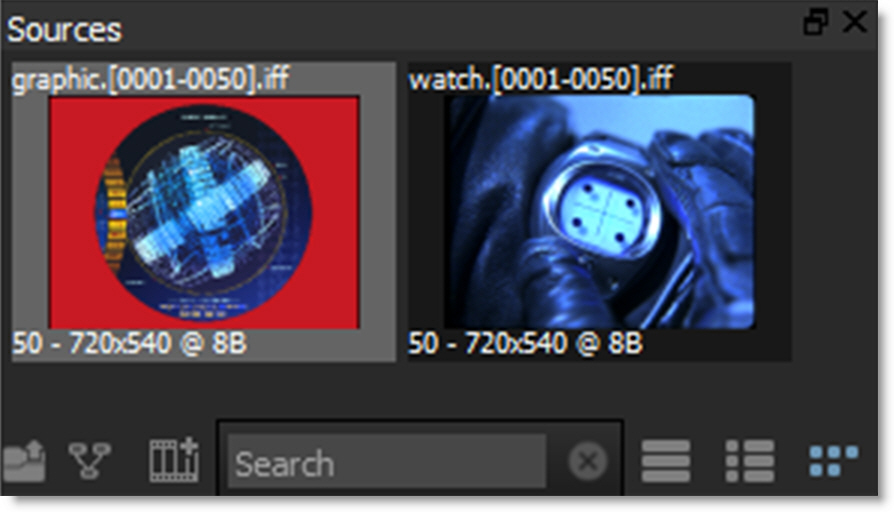
3 Press Ctrl/Cmd-N and create a session using a Composite template.
The source node is automatically connected to an Output node and the Composite workspace is selected which provides ample space to create trees.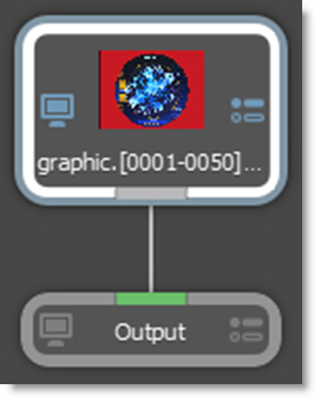
4 Select the Nodes tab at the bottom of the screen.
Silhouette is a node based system and different nodes are used for various functions.The node groups are displayed and are organized into Color, Composite, Diffusion, Filter, Film Lab, Image, Key, Light, Silhouette, Special Effects, Time, Tints, Transform and Warp groups.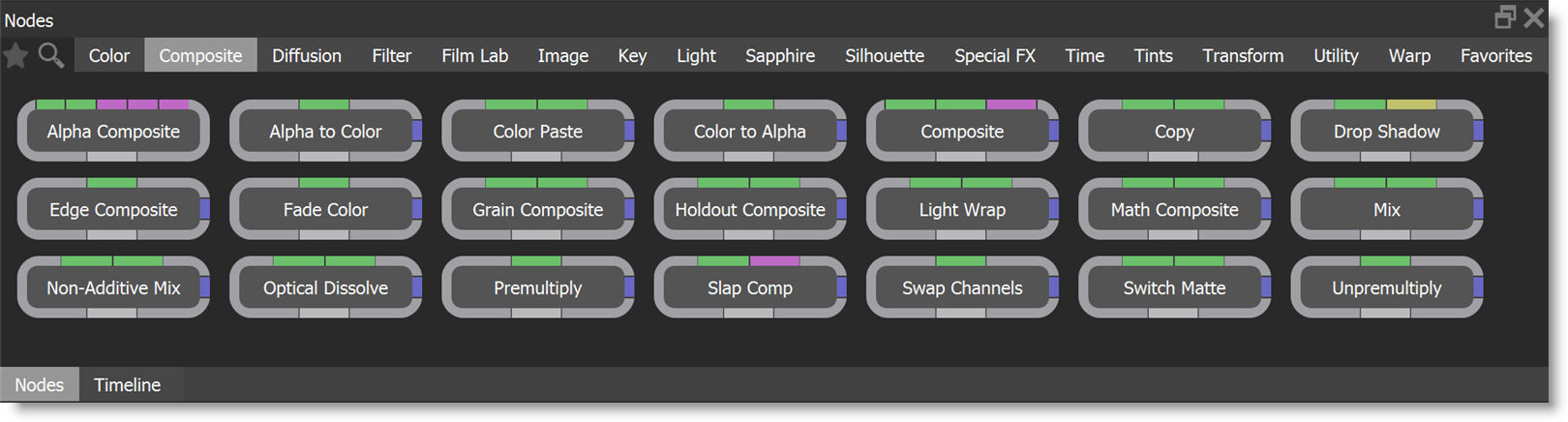
You can search for nodes by clicking the Search icon at the top left of the Nodes window. Type in the node that you want to search for and it will appear. Click the Search icon when done to return to the normal Nodes window view.
5 Select the Composite category and the nodes for that group are displayed.
6 Click and drag a Composite node to the Trees window and drop it onto the existing node wire between the source and output nodes.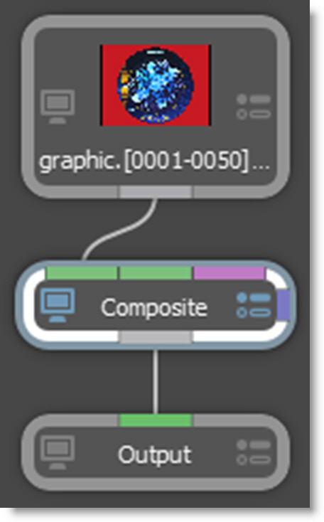
The node wire will automatically grab on to the Composite node. In case you were wondering, the different colored bars on the border of the node allow you to connect into and out of it.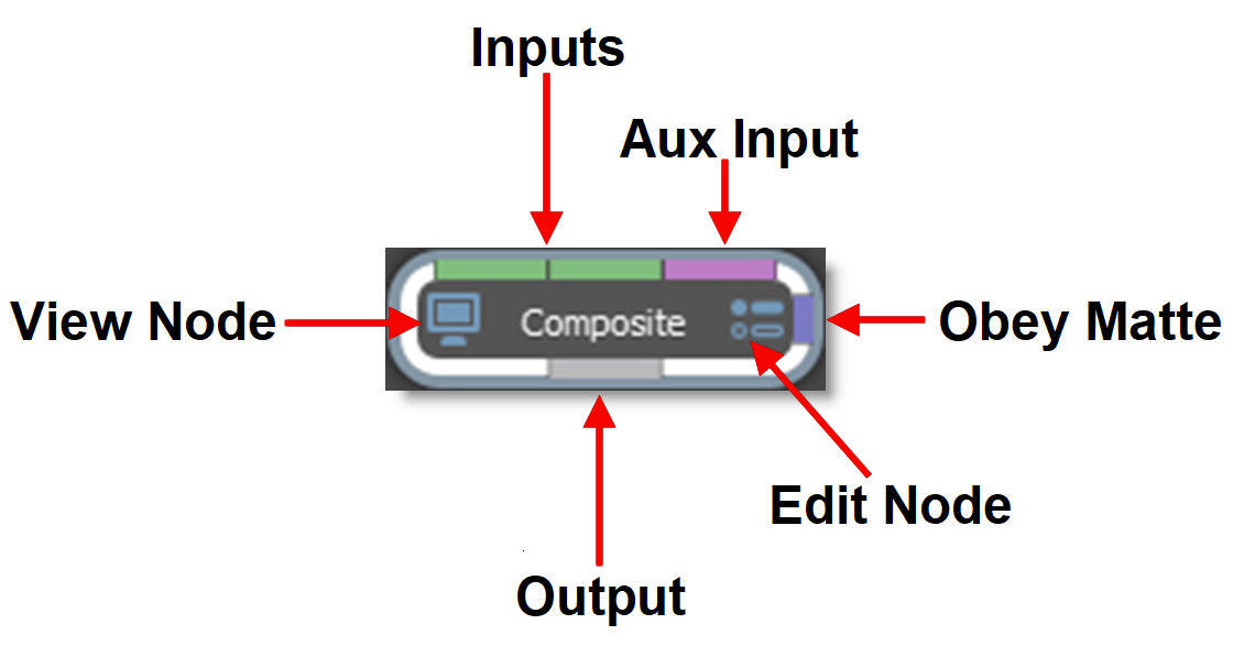
The Composite node can use either two or three inputs.
• Two inputs: Foreground RGBA and Background
• Three inputs: Foreground, Background, Matte
Note: You can change Composite’s input order with the User Interface > Trees > Input Order preference. By default, FG, BG is selected, but you can change it to BG, FG if you’d like.
7 Drag your background clip from the Source window to the Trees window.
8 Click on the background clip’s output port and drag to the Composite node’s background input (middle input).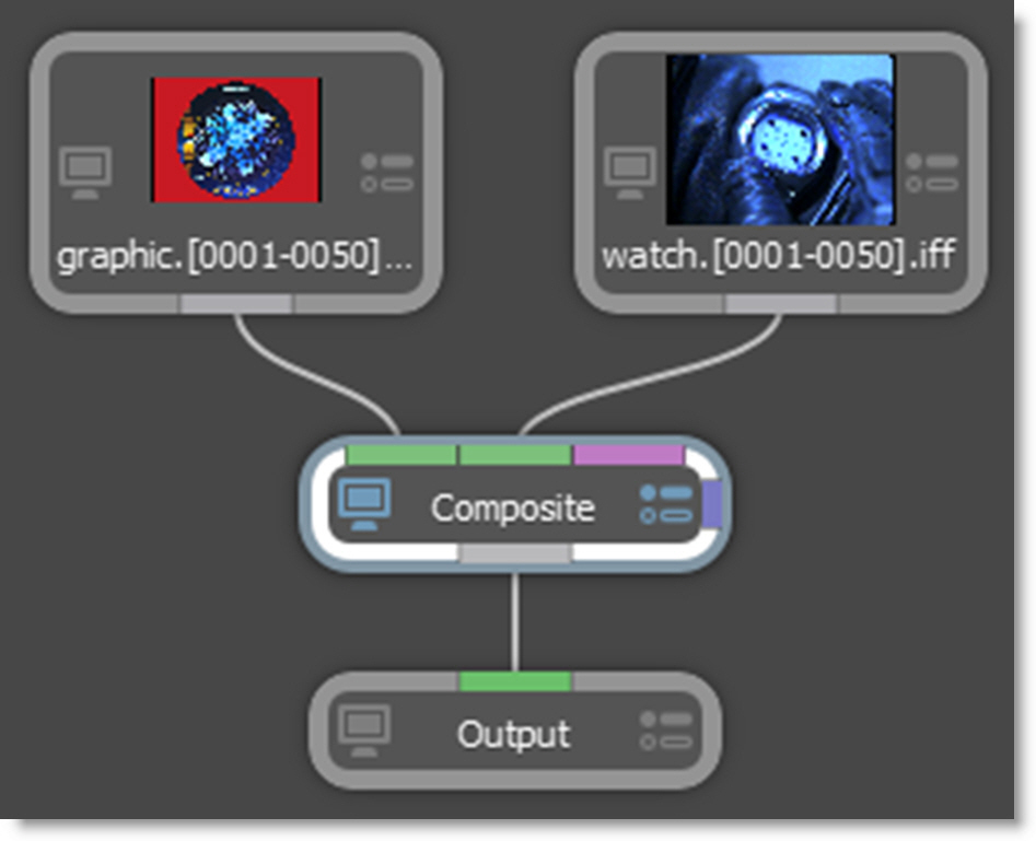
Silhouette is a straight, unmatted compositor and its composite nodes expect unpremultiplied images. In addition, it is best practice to unpremultiply before color correcting premultiplied images so as to avoid unexpected results. If you are working with premultiplied images, you have the following options:
• In the Source parameters, identify the alpha as Premultiplied. This will unpremultiply it.
• Unpremultiply the image within the Composite node.
• Use a Composite > Unpremultiply node before the premultiplied image hits the Composite node.
9 Single-click in the center of the Composite node to view and edit it.
When a node is single-clicked, a couple of things happen. First, it is loaded into the Viewer so you can see its affect on the image. Second, its parameters are loaded into the Node parameters window so its controls can be edited. You can tell which node is being viewed and edited by the state of the View and Edit Node icons on the node. They are colored blue when enabled.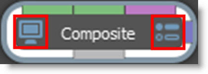
When you have multiple nodes, you can view one node while editing another. Just click on either the View Node or Edit Node icons. Let’s connect another node.
10 From the Image tab, click and drag a Roto node to the Trees window. Press the Ctrl/Cmd key before dropping it onto the background source clip.
This creates a new branch.
11 Hook the Roto node’s output (far left output port) to the Obey Matte input (right edge of node) of the Composite node.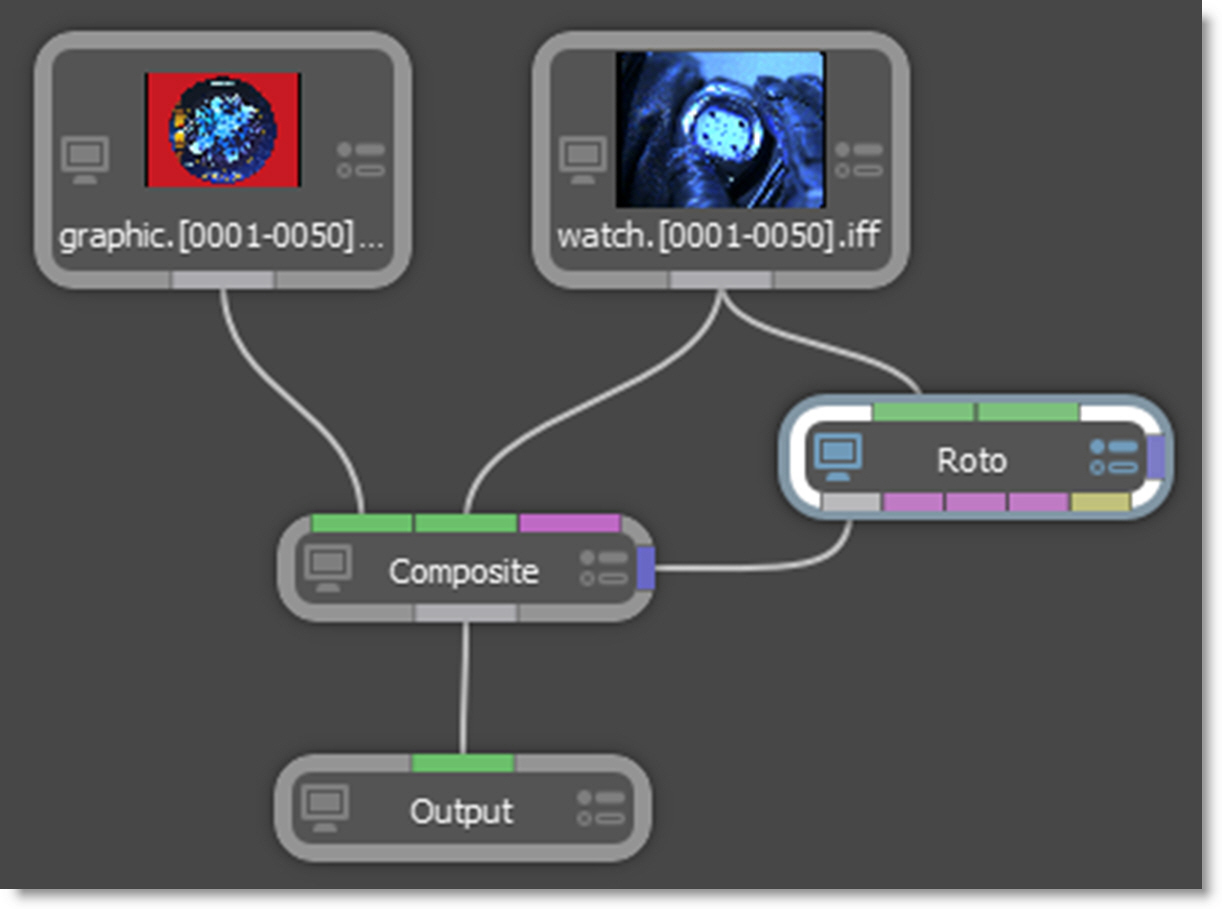
Whatever is plugged in to the Obey Matte input will constrain or limit the effect of the node.
12 Click the View Node icon on the Composite node and the Edit Node icon on the Roto node.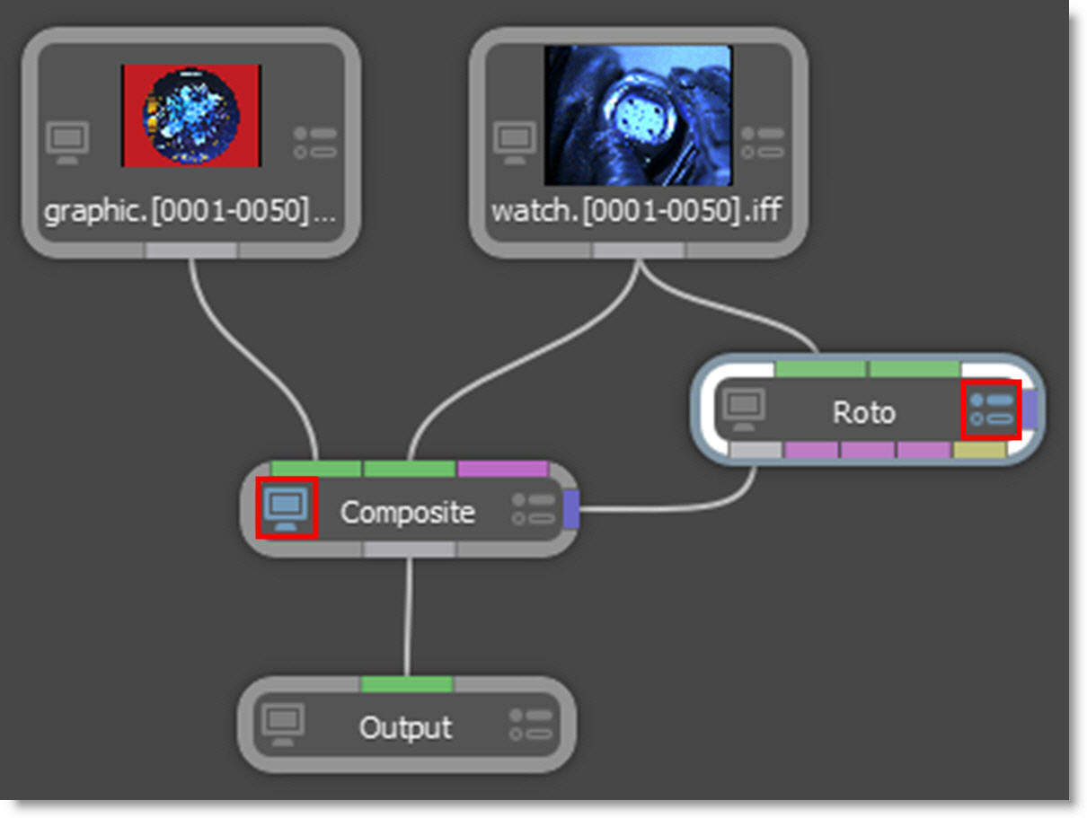
This configuration will allow you to view the Composite node while editing the Roto node.
13 Click the Circle icon located on the left side of the Viewer and drag out a circle over a portion of the foreground that is being composited.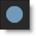
14 Click the Edit icon on the Composite node, switch to the Obey Matte tab in the Node window and enable Obey.
Now, the composite only occurs in the area defined by the Obey Matte input.
For all the ways you can add and connect nodes, see the Adding and Connecting Nodes sections for more information.
Favorite Nodes
Nodes can be tagged as a Favorite allowing them to be grouped separately in the Favorites tab of the Nodes window.
1 Select a node in the Nodes windows by single clicking on it.
2 Tag the selected node as a Favorite by pressing the Favorite icon at the top left of the Nodes window.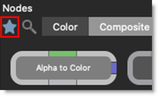
3 Click on the Favorites node tab to see the favorite nodes.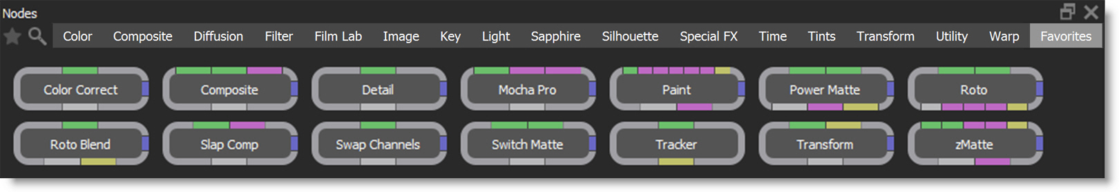
Organizing The Tree With Dot Nodes
With complicated trees, the node connections can get a bit messy. To deal with this, the Dot node can manually route node connections in a cleaner fashion.
1 Create a Dot node by Alt-clicking on an existing node connection.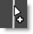
You can also add the Dot node from the Utility node group like any other node.
2 To drag additional outputs from the Dot node, hold Alt over the dot and when the input/output ports appear, drag from the output port to the desired destination.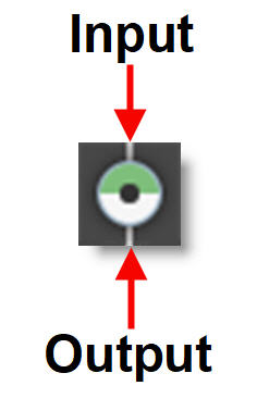
Dot nodes strategically added to connections tidy up the tree.
Multiple Object Lists, Node Or Object Windows
Creating Additional Windows & Locking Them
Multiple Object Lists, Node or Object windows can be created and locked to any node in the tree regardless of which node is active. In each of these windows, there are Add Dock and Lock Node icons.
1 Click the Add Dock icon in either the Object List, Node or Object windows.
A new Object List, Node or Object window is added and incrementally numbered.
2 Press the Lock Node icon to enable it.
The Object List, Node or Object window is now locked to the current node. Clicking on another node has no effect on the locked window. This workkflow allows you to have multiple windows locked to different nodes.
Multiple Filtered Object Lists
Multiple Objects Lists in conjunction with search filtering can be used to organize left or right stereo objects, A or B morph shapes or anything else for that matter.
1 Set up a stereo session with objects in the left and right views or a morph project with A and B shapes.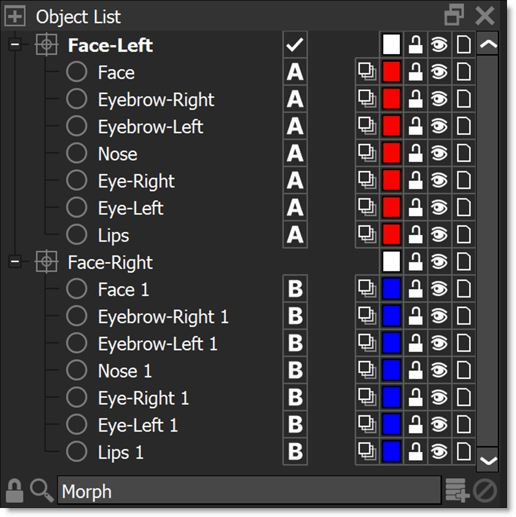
2 Click the Add Dock icon to create another Object List.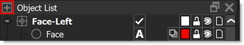
Each additional Object List is incrementally numbered and is displayed as a tab below the Object List.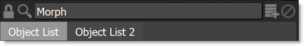
The Object Lists are identical until you filter them with the Search icon. With two Object Lists open, for instance, you can filter one on /l (left view) and the other on /r (right view) for stereo projects or filter on /a (A side) in one and /b (B side) in the other for morphing. If you then switch an object’s view assignment from left to right or from A to B, it will cause it to jump between the two lists.
3 Enable the Search icon in the original Object List.
4 In the Search field that appears, enter /l if you are working in a stereo project or /a if in a morph project.
The Object List now only displays left view objects for a stereo project or A side objects for a morph project.
5 Enable the Search icon in Object List 2.
6 In the Search field that appears, enter /r if you are working in a stereo project or /b if in a morph project.
Object List 2 now only displays right view objects for a stereo project or B side objects for a morph project.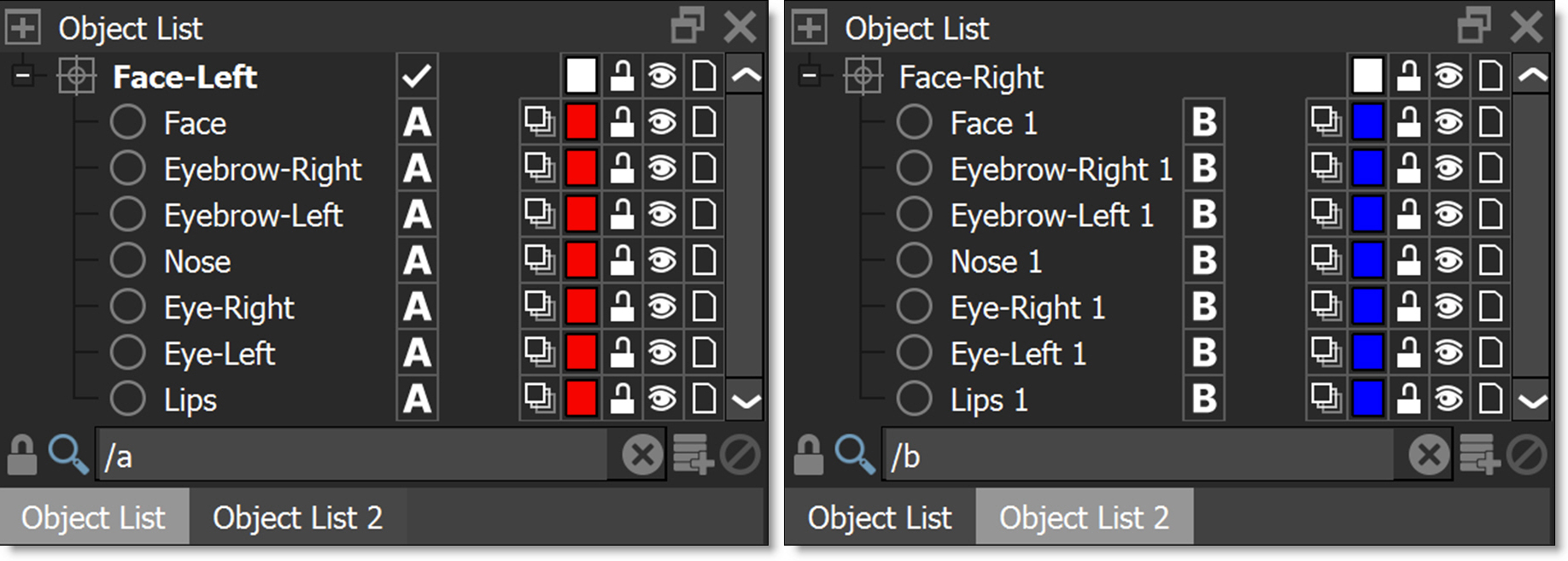
You can now easily switch between the Object Lists.
Note: Closing one of the added docks will also delete it.
7 Disable the Search icon when done to return to the normal Object List window view.
Compound Nodes
Compound nodes allow you to merge selected nodes into a single combined node, with parameters grouped by node for streamlined access within the Parameters window, enabling you to view one node while editing another. Customization is provided by adding, removing or renaming nodes and input/output ports as well as hiding parameters. Additionally, compound nodes can be published to a designated node group and are stored in an external location for reuse on other systems.
Creating Compound Nodes
1 Add the nodes to the Trees window to be included in the compound node and make sure to hookup source and output nodes.
Hooking up the source and output nodes define which input and output ports are used.
2 Select the nodes to be included in the compound node, but do not select sources or outputs.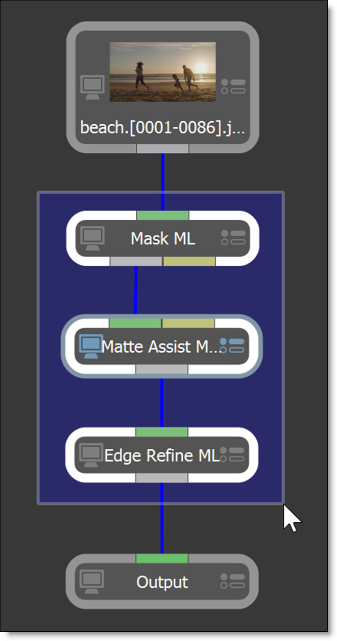
3 Right-click and select Create Compound Node.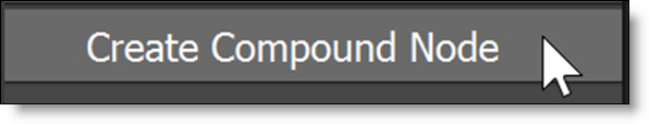
The selected nodes are combined into a new combined node and is represented by a stacked node icon.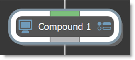
In the Parameters window, parameters are organized by node. You can edit one node while viewing another or click a node name to view and edit it at the same time.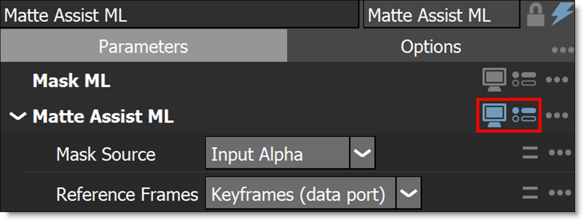
Hiding Parameters & Nodes
Parameters and nodes within the compound node can be selectively hidden.
1 To hide a parameter, click the options icon ... to the right of the parameter name and deselect Published.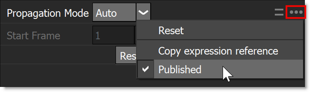
2 To hide a node, click the options icon ... to the right of the node name and select Hide Node.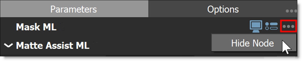
3 To show a hidden parameter or node, select the Options ... menu at the top right and select Show Hidden Parameters or Show Hidden Nodes.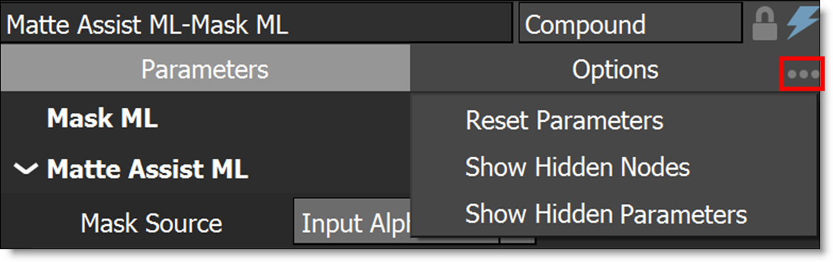
4 Once Show Hidden Parameters or Show Hidden Nodes is enabled, you can re-enable Publish for the hidden parameter and disable Hide Node for the hidden node.
Editing Compound Nodes
1 To edit a compound node, a) double-click on it or b) click on it to make it the active node, right-click and choose Edit Compound Node.
2 Here’s a list of edit operations that can occur in the Compound Node Editor:
• Add or delete nodes.
• Rename input/output ports and change their port ID by right-clicking on the input ports at the top of the Trees window or output ports at the bottom of the Trees window.
• Connect or disconnect a node to one of the input/output ports.
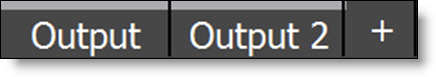
• Add new input/output ports by dragging a node connection to the + icon.

• Delete input/output ports by right-clicking and selecting Delete Port.
• Reorder the input/output ports by dragging them.
3 To exit the Compound Node Editor, click the Back icon at the top left of the Trees window.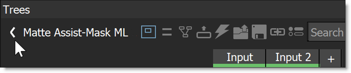
Publishing Compound Nodes
1 Click on a compound node to make it the active node.
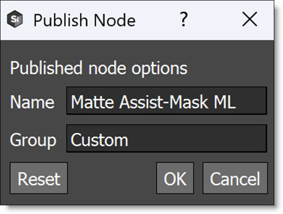
2 Right-click and choose Publish Compound Node, then enter the name and node group.
The published compound node now appears in the specified node group and is stored in /Home/Silhouette/extensions/nodes. If the compound node name is too long, it will be truncated in the Node view.
3 Hover over the compound node to display a tool tip of its entire name.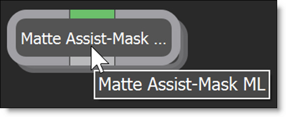
4 To change the compound node’s name and node group:
• Select Help > Open Extensions Location.
• Open the Nodes folder.
• Edit the nodeName.sfxnodes file in a text editor and change the label to rename the node and categories to change the group.
• Restart Silhouette.
5 To load compound nodes from a shared location, enter the path in Preferences > Extensions > Search Paths or set the SFX_EXTENSION_PATH environment variable to a ; separated list of paths.
Timebar Keyframes
Colored markers in the shuttle area signify where selected objects have keyframes. These keyframes can be moved to a new position. Objects that display keyframes in the Timebar are shapes, trackers and painted frames. Path keyframes are shown for shapes, position keyframes for trackers and painted frames when in the Paint node.
The color of the markers is determined by the object color. If multiple selected objects have a keyframe on the same frame, the most recently selected object's color has precedence.
1 Press Shift-Alt and hover over one of the colored markers.
2 When the cursor changes to a double arrow, click and drag the marker to a new location.
Timeline
The Timeline is an overall view of all animated parameters. It provides you with the tools necessary to view, edit, move or delete keyframes as well as change their interpolation type using a Curve Editor.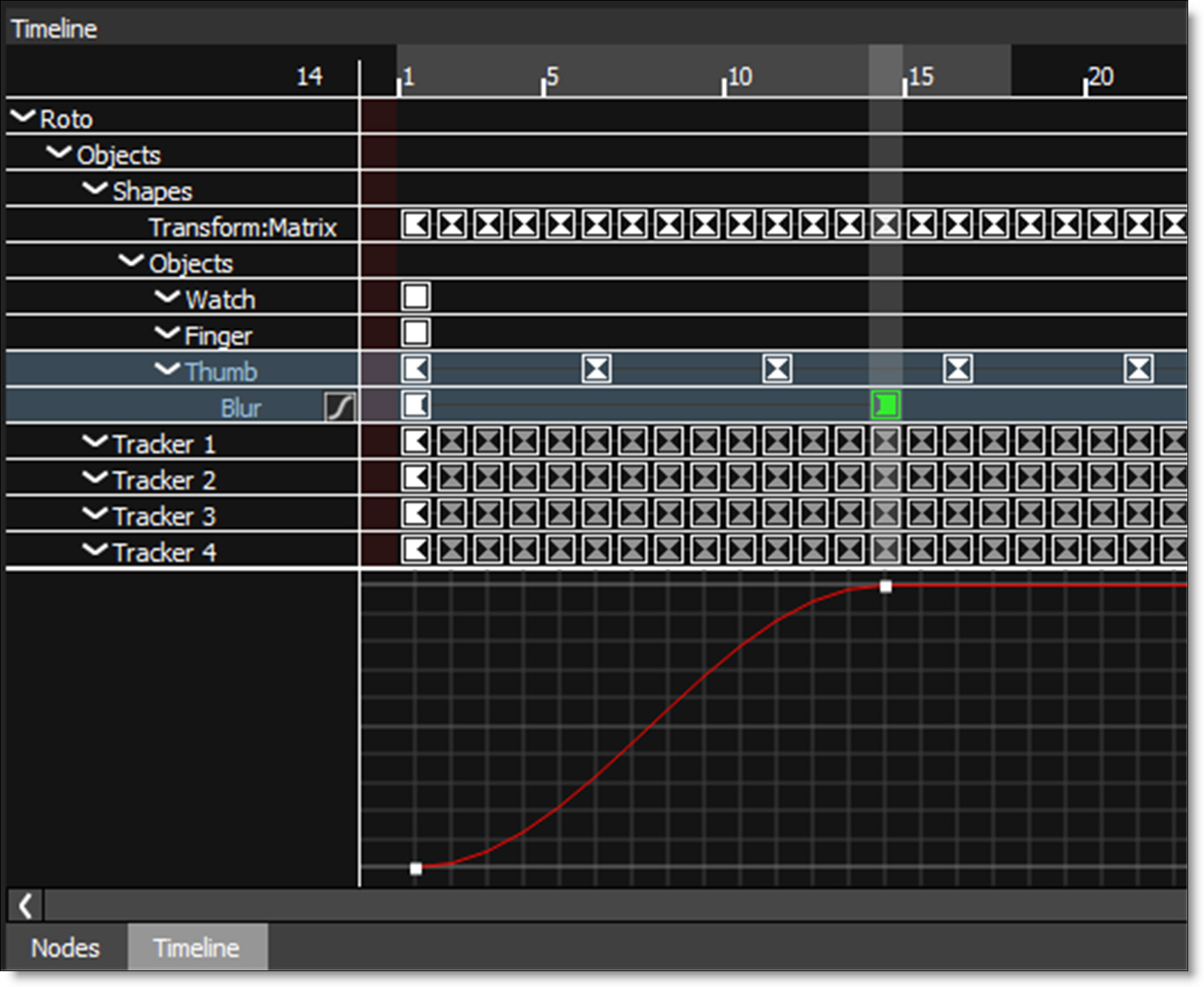
Zooming the Timeline In or Out
1 Use the scroll wheel to zoom the Timeline in and out.
or
2 Shift-Middle-mouse drag in the Timeline.
Panning the Timeline
1 Use the Spacebar and click and drag to pan horizontally or vertically in the Timeline.
Changing the Work Range
The Timeline displays the full session range with the work range displayed using a gray bar at the top of the Timeline.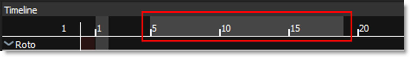
The work range can quickly be adjusted by:
1 Ctrl/Cmd-drag the ends of the work range bar to change the start and end.
2 Ctrl/Cmd-drag the work range bar to slide it forward and back while maintaining the duration.
Moving One Keyframe
1 Click on a keyframe to select it.
2 Drag the selected keyframe to its new time.
Moving a Selection of Keyframes
1 Click on the starting keyframe to select it.
2 Shift-click on the ending keyframe.
A range of keyframes is selected.
3 Click and drag one of the selected keyframes to the new location.
All selected keyframes move to the new location.
Adding a Marker
1 Move the Timebar to the desired frame.
2 Right-click in the Timeline and select Marker > Create/Edit.
3 Enter the marker text and click OK.
A light blue marker is displayed at the top of the Timeline.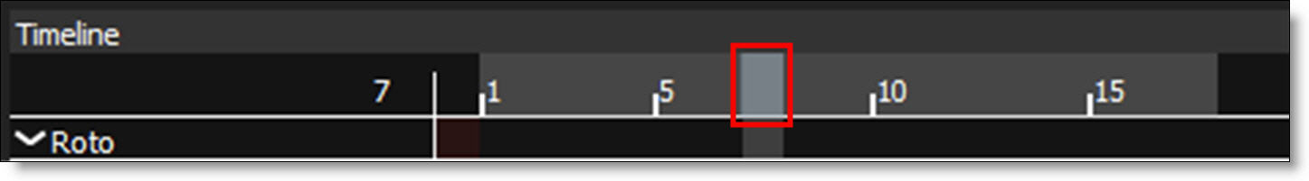
Curve Editor
The Curve Editor is a view mode in the Timeline that allows you to work with keyframe animations expressed as curves on a graph. It allows you to visualize the interpolation of the animation.
1 Animate a parameter by setting a couple of keyframes.
Once a parameter is animated, the Curve Editor icon appears to the right of the parameter in the Timeline.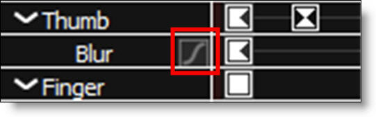
2 Enable the Curve Editor icon.
The Curve Editor appears at the bottom of the Timeline.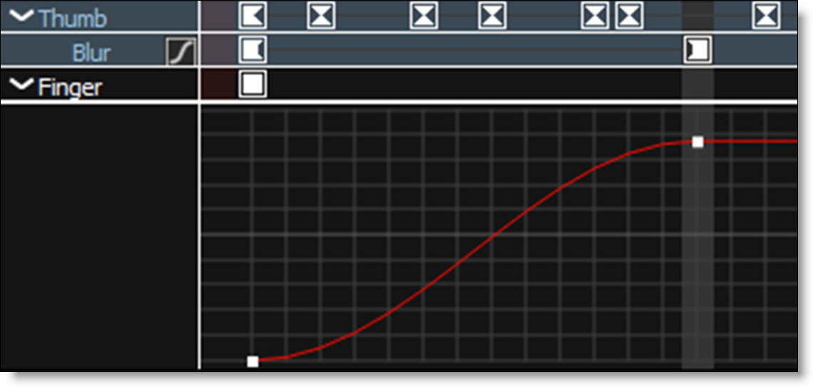
3 Use the + or = keys to zoom in, the - key to zoom out or Space Bar-move mouse to pan the Curve Editor.
4 Click and drag a point to move it and Alt-click on the curve to add a new point.
5 Right-click on a keyframe in the Timeline or a point in the Curve Editor to bring up the pop-up menu.
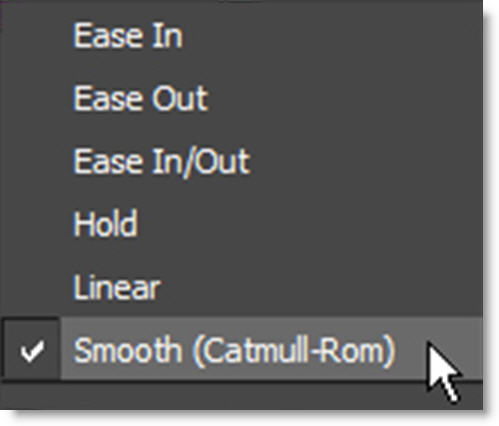
The pop-up menu allows you to change the keyframe interpolation.