Morphing
Image morphing can take place on stills as well as moving images. Morphing has been traditionally used to transform one object or person into another and more recently to seamlessly transform a live action element into a CG (computer generated) object and vice versa.
Assigning Inputs
A and B inputs are required for a morph.
1 Choose two images to morph together and wire them into a Morph node.
The A input (A-roll) is considered the source and the B input (B-roll) is considered the target. The A-roll will morph into the B-roll.
Create A-roll and B-roll Shapes
1 Select View > A and create shapes for the A-roll image. Shapes should be added to key areas of the image. When doing a facial morph, shapes should be placed for the face, eyes, eyebrows, nose, nostrils, mouth, lips, etc. You can use both open and closed shapes.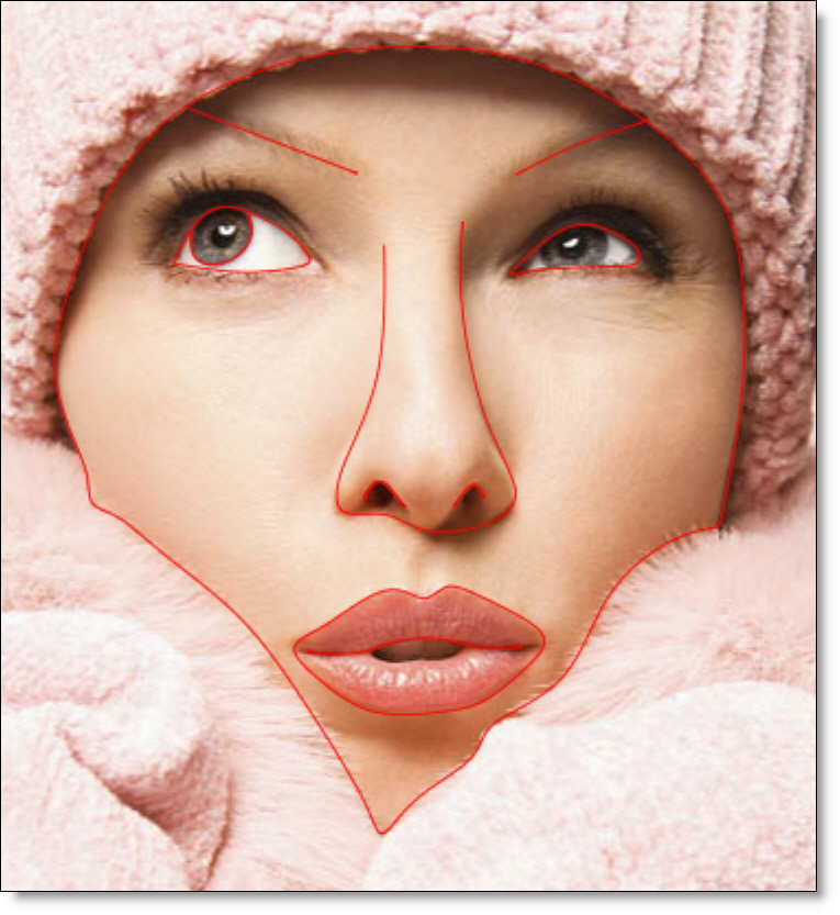
The A-roll shapes are automatically colored red.
2 If necessary, keyframe the position of the A-roll shapes.
3 Select View > B and create shapes for the B-roll image.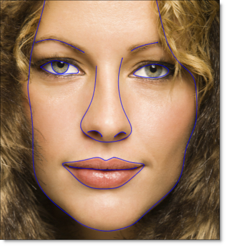
The B-roll shapes are automatically colored blue.
4 If necessary, keyframe the position of the B-roll shapes.
Joining Shapes / Adding Correspondence Points
Joining shapes specifies the direction of a warp.
1 Select the Correspondence (C) tool and join similar shapes.
For instance, the shapes for the eyes in the source image are joined to the shape for the eyes in the target image, mouth shapes to mouth shapes, nose shapes to nose shapes--you get the idea.
2 For the newly joined shapes, add additional correspondence points to the areas where the shapes change direction by Alt-clicking on a selected shape.
Setting the Distortion and Transparency
The Distortion parameter warps the image from the A-roll to the B-roll shapes while the Transparency dissolves between them.
1 Change the View to Output.
The Output view is where you can see the actual morph.
2 Select the Node parameters tab.
3 Set the Distortion to 0 at the start frame and 100 at the end frame.
4 Set the Transparency to 0 at the start frame and 100 at the end frame.
5 If you’d like, you can set the Distortion and Transparency to start and end at different times in the clip to create a more natural looking morph for your particular clip.
6 For faster interaction, you can use a lower quality proxy image by using the Proxy pull-down menu above the Viewer.
Previewing the Morph
The Viewer can display a wireframe preview to quickly visualize the morph.
1 Select View > Wireframe. You can also use Alt-W to toggle the wireframe view mode on or off.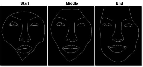
2 Press the Play button in the Timebar.
Silhouette will play a wireframe representation of the A-roll shapes morphing into the B-roll shapes.
3 Change the View to Output and press 0 to turn off the shape display. This will allow you to see the image better.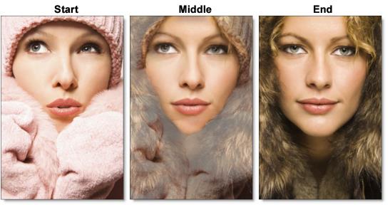
4 Press the Play button.
Silhouette will render each frame. If you have enough RAM to fit the clip into memory, it will playback in real time once it is completed.
5 If you see artifacts in the preview, go to the Node tab and change the Precision to Normal first and then Better if you still see artifacts.
Note: By default, the precision or quality of the warp is set to Draft.
6 For faster processing, you can use a lower quality proxy image by using the Proxy pull-down menu above the Viewer.
7 Press 0 again to turn shape display back on.
Adjusting the Morph
There are a number of ways to modify the look of the morph. By default, shapes and layers inherit their Distortion, Transparency and Depth from the Morph node settings. To “override” the value at the layer or shape, click the Override icon (dot) to the right of the numeric field and the parameter will override the parent.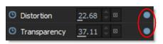
1 Override the Distortion and Transparency to have independent control over these parameters at either the layer or shape.
2 Use barrier shapes (unjoined shapes) to tack down areas and keep them stationary.
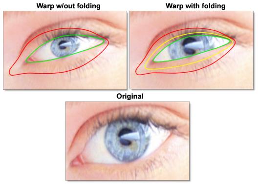
Folding
Sometimes the warping of a pair of joined shapes can overtake other shapes (joined or barrier). The overtaking shapes will necessarily fold over or under the shapes they overtake. For instance, you can warp eye lids over a pupil without distorting the pupil, as seen below.
1 Select View > A.
Viewing the A roll while creating and editing shapes will give faster interaction than View > Output.
2 Create source and target shapes.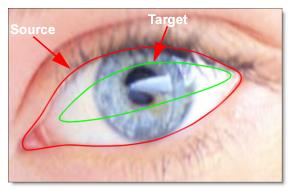
3 Select the Correspondence (C) tool and join the source to the target shape.
The source shape describes the current form of the object, while the target shape describes where you want it to fold.
4 Add correspondence points where necessary.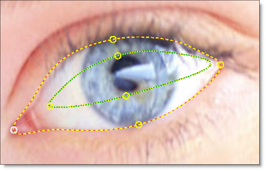
5 Create a barrier shape by copying and pasting the source shape.
Note: Folding can happen even with non-barrier shapes. Folding happens anytime one shape crosses over another.
6 Size the barrier shape to be slightly smaller than the source shape.
By using a barrier shape, the source shape will appear to fold over or under (depending on shape order in the Morph node's Object List) as it is transformed into the target shape.
7 In the Object List, arrange the barrier shape to be below the source and target shapes.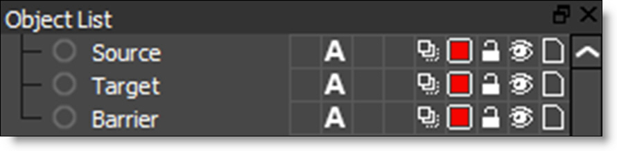
The upper level shapes or layers will appear to fold over the lower, barrier shape. The portion of the image between the barrier shape and target shape is not affected.
Note: The rendering order in the Object List is from bottom to top, so objects that are higher up are rendered in front of objects lower down.
8 Select the Node parameters tab.
9 Change the View to Output.
The Output view is where you can see the actual warp.
10 Set the Distortion to 100.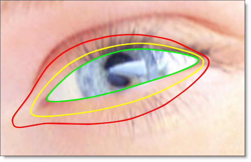
The eyelid folds over the eye creating a blink effect.
Check out the difference between the warp with and without folding.