Morph
Description
Understanding the concepts of warping and morphing will allow you to get the most out of the Silhouette software. Silhouette's morph node uses a “shape based” approach. Our company's founders include the inventors of this approach for which a Scientific and Technical Achievement Award was given by the Academy of Motion Picture Arts and Sciences.
Warping is a geometric or spatial distortion of an image. A morph is two or more synchronized warps composited together using location specific dissolve criteria specified by the artist.
As the term “shape based” implies, the artist creates shapes using the same tools as the Silhouette Roto node. In general, two shapes are paired together, one being the “source” and the other being the “target.” The exception to this can be an unpaired shape to be used as a “barrier.”
Silhouette warps source shapes to match target shapes (and in a morph, the target shapes simultaneously warp towards source shapes). As shapes warp, the image underneath the shapes (and surrounding areas) warp along as well as if the image were being stretched like a sheet of rubber.
Silhouette's warping technology provides a rich set of controls over the specific effect of the warp. These include the ability to precisely control correspondence between source and target shapes allowing the artist to specify not only that one shape should warp to another, but what part of the source shape to warp to what part of the target shape.
The Silhouette morph node also allows for the precise control over how shapes might fold over other shapes. Folding is a powerful feature which can best be understood by imagining pulling a blanket rather than a sheet of rubber. Snatching a piece of the blanket and pulling it can do one of three things. It can move the area of the blanket ahead of its motion out of the way. It can fold on top of the area in its way. Or, it can fold behind the area in its way.
All of these controls are necessary to create seamless, invisible effects.
Warps
Image warping can take place on a still as well as moving images. Warping can be used to enhance or exaggerate features, adjust sizing of image elements, create talking animals, for example, or other types of image deformation.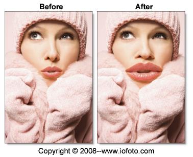
Go to the Shape Based Warping tutorial to see how it works.
Morphs
Image morphing can take place on stills as well as moving image. Morphing has been traditionally used to transform one object or person into another and more recently to seamlessly transform a live action element into a CG (computer generated) object and vice versa.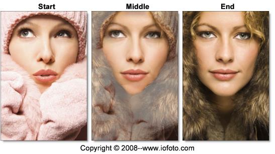
Since shapes are required for warping and morphing, it has its own shape tools similar to those in the Roto node. See the Roto Node for more information.
Go to the Morphing tutorial to see how it works.
Node Group
Warp, Silhouette.
Node Parameters
When the Morph node is being edited in the Trees window, parameters specific to the Morph can be adjusted in the Node parameters.
Distortion
Controls the amount of deformation for joined shapes.
Transparency
Controls how the A-roll and B-roll images are mixed together.
Precision
Sets the computing precision of the Morph node. There are Draft, Normal and Better choices.
Draft
Draft mode provides a fair representation of your work but has clearly visible defects. It is fast, interactive and very responsive, but is not intended for finished work.
Normal
Assuming you are using a reasonably modern machine, Normal can be used in most interactive situations and is sufficient for finished work.
Better
Better is slower than Normal, though still interactive on modern processors. It can be used for final renders although you should pre-check the final render before submitting it to a render farm.
Note: Image areas immediately below shapes will be the same in all modes. Image areas which are pulled and pushed by nearby shapes will differ between the modes.
Use Input Alpha
Ignores the Transparency value and just warps the input alpha.
Output Alpha
Cutout
Outputs an alpha of the final morphed shape.
Transparency
Outputs the alpha of the final morph transparency.
Motion Blur
Motion blur is the directional blurring of rapidly moving shapes. Enables Motion Blur for the Morph node.
Go to the Motion Blur tutorial to see how it works.
Parameters set on the Morph node provide the (potentially keyframed) default values for all shapes in the node. To allow shapes to have values different from those of the node, use the Morph Shape parameters.
See the Inheritable Parameters section below.
Shape Parameters
All of the roto tools contained in the Roto node are available in the Morph node and contain parameters specific to warping and morphing. This includes B-Spline, Bézier or X-Spline shapes as well as point and planar tracking.
Note: When two shapes are joined, the controls indicated below are taken from the source shape only. Settings from Target shapes are not used.
Outline Color
Sets the color of selected shape’s outlines. Shapes created while viewing the A-roll will automatically have a different outline color than those created while viewing the B-roll.
Inheritable Parameters
By default, shapes and layers inherit their Distortion and Transparency from the Morph node settings. To “override” the value at the layer or shape, click the Override icon (dot) to the right of the numeric field and the parameter will override the parent.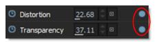
Distortion
Controls the amount of deformation for joined shapes.
Transparency
Controls how the A-roll and B-roll images are mixed together.
Barrier Strength
Being shape to shape based, the Silhouette Morph node will always “hit its mark”. That is, pixels directly underneath a shape will arrive exactly underneath the shape to which it (the source shape) is joined. This also means that the influence of a warp stops dead at barriers (unjoined shapes).
The Barrier Strength control, available only for unjoined shapes, lets barriers pass through a portion of a warp's influence. At a value of zero, the influence of the barrier shape is almost completely eliminated. At a value of 100 percent, the barrier is at 100 percent strength, and the influence of a warp stops dead. All unjoined shapes default to 100 percent.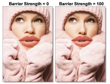
Note: Be careful when using barriers in morphs. Since a barrier is unjoined, it can exist only in one of the warps, not on both. This means there is the potential to see unwanted artifacts since the two sides of the morph are no longer warping in concert.
See the Barrier Shapes section for more information.
Edge Density
When rendering warps and morphs, Silhouette utilizes an edge density parameter which subdivides the shape between correspondence points. The higher the Edge Density, the closer the shape matches the curve that you originally created. Under normal circumstances, the default value of 100 should be fine.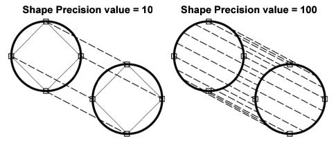
If you adjust the Edge Density, don’t automatically set it to the highest setting as this is unnecessary and could lead to longer rendering time. Increasing edge density might be needed for shapes whose source or target are physically large relative to image size and have few correspondence points.
For example, if a joined shape stretched from the left to right edges of your image and had a single correspondence point with an edge density of 100, the perimeter of the whole shape would be represented by 100 far apart vertices. You could add a second correspondence point to halve the distance between vertices or you could increase the edge density to accomplish the same result. One method can be preferable to the other, for instance when there is an image feature, it would be logical to join from source to target with an additional correspondence point. If there isn't an image feature, simply increasing edge density means there is potentially less to keyframe.
Shapes whose source and target are physically very small relative to image size can actually benefit from reducing their edge density.
Note: Edge Density determines how closely the perimeter of the rendered shape matches the original B-spline, X-Spline or Bézier shape.
Motion Blur
Motion blur is the directional blurring of rapidly moving shapes. This parameter turns Motion Blur on or off on a shape by shape basis. The default is off.
Generate Alpha
Determines whether or not a shape contributes to the alpha channel. This is on by default.
A/B Shapes
Morph Shapes create themselves in the proper “roll” when viewing A or B. If viewing any other View mode, creating a shape will default to A. The Object List shows the A/B state and clicking the A or B will toggle the shape to the other roll. Viewing A or B will only show A or B shapes, as appropriate. Creating a shape on the B-roll will automatically set the shape color to blue. Also, Select All in A or B will only select A or B shapes, respectively.
Correspondence Tool (C)
Understanding Correspondence Points
Correspondence points are a critical part of achieving superior results in the Morph node. Imagine you have a bendable shower rod. The shape that you bend the shower rod into represents the shapes you use to outline features in your images. Now attach the shower curtain using rings that can slide anywhere along the shower rod. These rings are like correspondence points.
Your image is printed on the shower curtain. The shower rod defines how the border of the image feature gets deformed in combination with how you line up the shower curtain using the sliding rings along the shower rod.
The combination of shape and correspondence point (shower rod and shower curtain rings) makes a warper that is incredibly more precise than a warper without the combination of these features.
Correspondence Points Workflow
Shape correspondences determine how to transform the areas of the image defined by your source and target shapes. This is accomplished by selecting and joining shapes in a particular order.
Joining shapes specifies the direction of a warp. That is, which shape of a pair of joined shapes is considered to be the source and which is the target. When using a morph to transform one person’s face into another, it is necessary that you join the shapes from one image to another. For instance, the shapes for the eyes in the source image are joined to the shapes for the eyes in the target image, mouth shapes to mouth shapes, nose shapes to nose shapes--you get the idea. Without the joining process, Silhouette cannot know that shapes relate to each other.
Every joined shape has correspondence points which are only visible when using the Correspondence tool. Since barrier shapes are not joined, they do not show any correspondence points.
When two shapes are joined, correspondence points define how the perimeter of the source shape matches to the perimeter of the target shape.
Using Correspondence Points
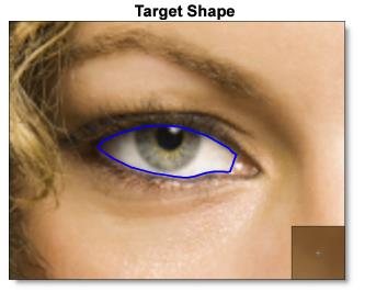
To illustrate the use of correspondence points, source and target shapes are created on two different images. The source shape is outlined in red and the target shape is outlined in blue.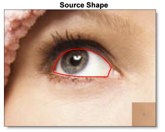
Joining and Unjoining Shapes
Whether you are warping or morphing, you must join together two shapes to cause movement from the source to the target.
Joining Shapes
When you join shapes, a shape correspondence is established in the image areas defined by these shapes. To join shapes, select the Correspondence tool, click the source shape and drag a line to the target shape, and release the mouse button to join the shapes. Circles appear on each shape which indicate the actual correspondence points. The dotted lines which flow around the shapes are lines of correspondence which show how the entire perimeter of the source relates to the entire perimeter of the target.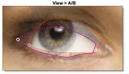
• Two A-roll or B-roll shapes can be joined to create a warp.
• Join one A-roll shape to one B-roll shape to create a morph.
Note: Switching to A/B View mode allows you to see both the A-roll and B-roll shapes simultaneously. You can then join shapes from the A-roll to the B-roll and vice-versa.
When joined shapes are selected, a modified bounding box appears around both shapes. The source shape has long dashes in the bounding box, while the target shape’s bounding box has short dashes.
Unjoining Shapes
You can unjoin shapes at any time which allows them to be then joined to other shapes. To unjoin shapes, select the Correspondence tool, select the source or target shape, right-click on the shape and choose Unjoin from the pop-up menu.
Once unjoined, the shape’s bounding boxes revert to a solid line indicating that they are unjoined.
Correspondence Point Positioning
When shapes are joined, Silhouette adds a single correspondence point on the shapes. It is best to add and position these points so that logically similar features are connected together. Correspondence points serve as guides that define the location of identifiable areas on a shape.
Note: Never assume that correspondence points automatically line up to the control point of a shape. They often have to be lined up to the desired image features.
Poor Correspondence Point Placement
Poorly placed correspondence points results in warping artifacts. You can see the correspondence lines wrap around the outlines of each eye. The correspondence point pair is not specifying a correspondence relationship that is going to produce a good result.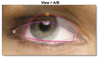
Performing a morph preview with these poorly aligned correspondence points produces a poorly aligned result.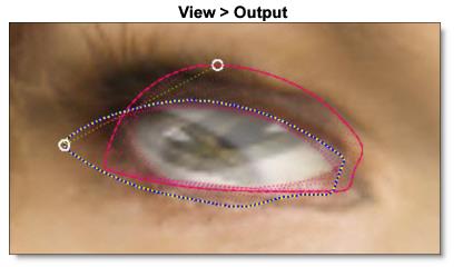
As a general rule, for which there are many exceptions, you want to align like features. Multiple correspondence points may be specified as shown below. This precisely pins down the relationship between the shapes exactly where you need finer control.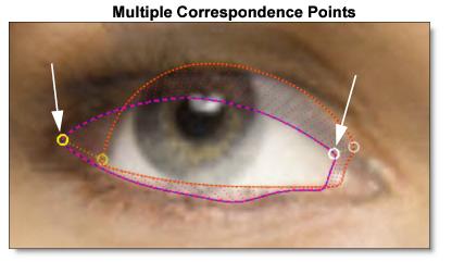
Getting Good Results
Let’s break down a complex use of correspondence points that gives the best possible results. Sophisticated correspondence point placement is especially necessary when there are multiple shapes in a small space, for instance where the eye outline is in close proximity to outlines for the iris and pupil.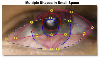
You will note that the eye outline has nine correspondence points.
The choice of these two sets of correspondence points is straight forward. They join the left-most eye points together and the right-most eye points together.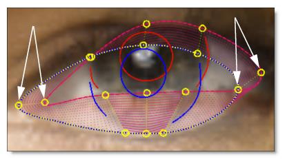
The next example shows how the correspondence points are used to maintain the relationship between source and target features. In this case, correspondence points were placed in such a way as to bisect both pupils. Even though these correspondence points are not left-most or right-most or even the same distance around each eye surround, they represent logically connected features between the source and target.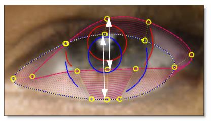
The last example shows how the relationship between the outline of each iris is maintained relative to the eye surround. These correspondence points are extremely important. The outline of each iris ends before it touches the eye surround. This is because the position of the iris outline is going to slide relatively against the eye surround. By not overlapping the iris outline and the eye surround, you are giving the image a little room to stretch without folding.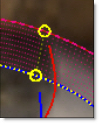
You will be able to visualize where this type of sliding of two shapes against each other may present a problem using the wireframe preview.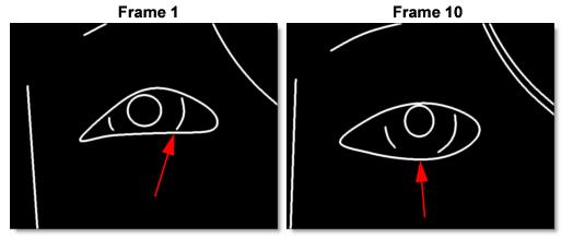
The arrows show where on the eye surround shape the iris shape connects. You can see how from frame 1 to frame 10, the place where iris meets the eye surround slides relative to the eye surround (compare to the position of the iris, for example).
Swapping Source and Target Shapes
When shapes are joined in the wrong order, they can be swapped using the Swap Joined option. To swap source and target shapes, select the Correspondence tool, select the source or target shape, right-click on the shape and choose Swap Joined from the pop-up menu.
Reverse Shape Orientation
Reverses the order of all control points on all keyframes. Similar to the Reverse option in the Reshape tool pop-up menu, Reverse Shape Orientation is useful when you are trying to join two shapes where the control points go clockwise in one and counter-clockwise in the other. In this case, the correspondence points would iterate in different directions and the lines would cross each other. Reversing the points of one of the shapes would make them go in the same direction and the correspondence would be correct.
Inserting Correspondence Points
To increase the precision of a complex shape, increase the number of correspondence points. To add a correspondence point, select the Correspondence tool and Alt-click on a selected shape.
The edge density at the insertion point is effectively doubled by the addition of a new correspondence point. By dragging the new correspondence point, you move it to the desired location.
Deleting Correspondence Points
Correspondence points can be deleted at any time, but remember that you need a minimum of four correspondence points. To delete a correspondence point, select the Correspondence tool, select the correspondence point and 1) press the Delete key or 2) right-click on the correspondence point and select Delete from the pop-up menu.
Note: Correspondence points can only be removed one at a time.
Selecting Correspondence Points
Before a correspondence point can be adjusted, you must first activate the Correspondence tool in the Toolbar and select a joined shape. Correspondence points are colored yellow. Click on a correspondence point to select it.
Adjusting Correspondence Points
Once selected, correspondence points are moved by simply dragging them to the desired location.
Barrier Shapes
Besides creating shapes to define areas that warp and morph, you can also use shapes as ways of restricting movement beyond certain parts of the image. These shapes are called barriers and tack down an area and keep it stationary relative to the warping caused by other shapes. Any unjoined shape will serve as a barrier.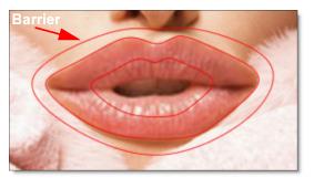
In the example above, the barrier shape will prevent any movement outside of the shape. Compare the results below.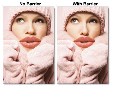
The barrier shape has successfully pinned down the image outside of its boundaries. Notice in the image on the right, the model's lips have clearly extended over her coat and the coat did not move.
Folding
Sometimes the warping of a pair of joined shapes can overtake other shapes (joined or barrier). The overtaking shapes will necessarily fold over or under the shapes they overtake. For instance, you can warp eye lids over a pupil without distorting the pupil, as seen below.
The images below show how folding can affect an image.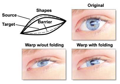
The choice of folding over or under is determined by the order of shapes in the Object List. In the above example, the source shape for the eye lid appears above the barrier shape for the pupil in the Object List. Therefore, the eye lid folds over the pupil.
Go to the Folding tutorial to see how it works.
Node Outputs
Output
Outputs the result of the morph or warp transformation.
Source Warp
Outputs the source warp.
Target Warp
Outputs the target warp.
Objects
Outputs tracked layers and shapes for use in nodes with Data inputs.