Viewer
Silhouette uses a Viewer for image editing as well as for clip playback. Some features include: viewing individual color channels, the simultaneous display of RGB and alpha channels, the selection of stereo views as well as the superimposition of shapes over images.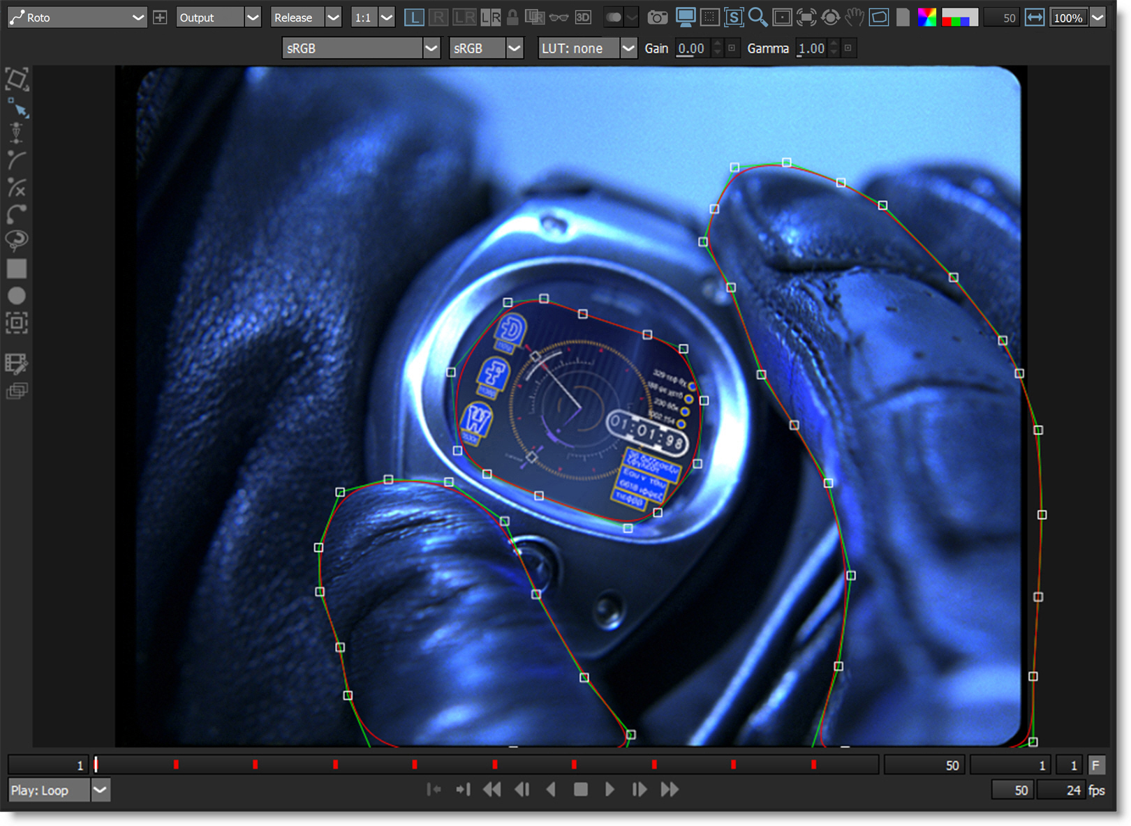
Node Selector
Selects the node displayed in the Viewer.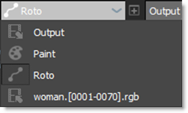
Alt-] cycles to next node in the menu, while Alt-[ cycles to the previous node.
New Viewer
The New Viewer icon opens additional Viewers that can be set to any node or view.
Note: Multiple viewers from the same node have the option of being synchronized in terms of zoom and pan using the Use Viewer > Synchronize Viewers preference.
View
Offers various View options for the selected node. The View choices will depend on the node.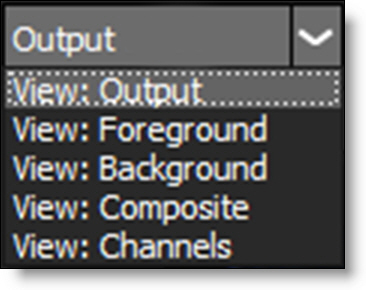
Update
Determines when processing takes place. The ~ key cycles through the Update modes.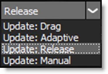
Drag
Tries to process at the current resolution as fast possible.
Adaptive
Tries to process as fast possible by first processing a 4:1 proxy and then full resolution.
Release
Processes once the mouse or pen is released. This the default setting.
Manual
Silhouette does not process. If you place the cursor within the Viewer window and hit the Enter key, Silhouette will manually process any changes.
Proxy
Sets the viewer resolution. The higher the number, the lower the resolution.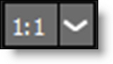
The higher the proxy setting, the more frames you can play.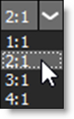
Note: You can only paint when the Proxy is set to 1:1. Otherwise, the cursor changes to a prohibition icon (circle-backslash).
1:1
1:1 keeps the image quality at full resolution.
2:1
2:1 lowers the image resolution by 1/2.
3:1
3:1 lowers the image resolution by 1/3.
4:1
4:1 lowers the image resolution by 1/4.
Stereo View Modes
The stereo view modes, which only show up when using stereo sources, determine whether you are working on the Left View, Right View or both the Left and Right Views at the same time.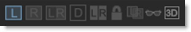
Left View (Shift-1)
Left View displays the left clip in the Viewer.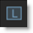
Right View (Shift-2)
Right View displays the right clip in the Viewer.
Left/Right View (Shift-3)
Left/Right View displays both the left and right clips in the Viewer at the same time.
Edit In Both Views
Controls editing in the Left/Right View.
Paint
When enabled, paint is added to both views simultaneously. When disabled, the left or right view is painted individually.
Roto
When enabled, shapes are edited in both views simultaneously. When disabled, shapes in the left or right view are edited individually. 
Depth (D)
Displays the Depth channel.
Stereo Split Mode
Only available once the Left/Right View is active, Stereo Split Mode determines whether or not the Left and Right Views are arranged horizontally or vertically.
Horizontal
Arranges the Left and Right Views horizontally.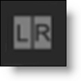
Vertical
Arranges the Left and Right Views vertically.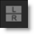
Stereo Align (Shift-4)
Stereo Align utilizes layers to line up two stereo clips which will effectively negate the offset between them. Aligning the clips in this manner allows painting on the same location of the Left and Right Views simultaneously, while for rotoscoping, it means shapes created for the Left View can be easily duplicated to the Right View in the proper position.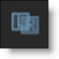
Note: Stereo Align can only be selected and used once a layer is selected.
When activated, Stereo Align uses a negative mode which inverts one of the views and mixes it with the other. This creates an embossed effect when similar image areas are not aligned.
Automatic Alignment
With a layer selected, stereo sources can be aligned automatically by pressing Shift-Alt and clicking on the image feature that you would like to align. Shift-Alt will function whether or not the Stereo Align view mode is enabled.
Note: Shift-Alt can only be used once a layer is selected.
Manual Alignment
Enable Stereo Align and drag on the Viewer to align the views.
When similar image features are perfectly aligned, you will see a solid gray color. The amount you move the view in Stereo Align mode is stored in the Stereo Offset parameter of the active layer which is set to animate by default. Animation of this parameter is needed for clips that contain depth changes.
Stereo Align Keyboard Shortcuts
Shortcut | Action |
|---|---|
Shift-Alt and click | Automatically sets the Stereo Offset horizontally |
Ctrl/Cmd-Shift-Alt and click | Automatically sets the Stereo Offset horizontally and vertically |
Click and drag in Viewer | Moves the Stereo Offset horizontally |
Ctrl/Cmd-drag in Viewer | Moves the Stereo Offset horizontally in finer increments |
Shift-click and drag in Viewer | Moves the Stereo Offset horizontally and vertically |
Alt-click in Viewer | Resets the Stereo Offset |
Arrow keys | Moves the Stereo Offset by 1 pixel |
Shift-Arrow keys | Moves the Stereo Offset by 10 pixels |
Ctrl/Cmd-Arrow keys | Moves the Stereo Offset by one tenth of a pixel |
Hold down Arrow keys | Moves the Stereo Offset continuously |
Anaglyph Preview (Shift-5)
Activates Anaglyph Preview mode so that you can check your stereo image in 3D using red-blue glasses.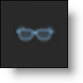
There are four anaglyph viewing modes that you can choose from. The default mode is set using the Viewer > Anaglyph Mode preference.
3D Preview (Shift-6)
Opens a 3D Preview window for displaying the stereo image. If you have multiple monitors, the 3D Preview opens full screen while on a single monitor system, it opens centered and smaller.
The 3D Preview has a pop-up menu containing zooming controls and display selection choices. The pop-up menu is accessed by right-clicking in the 3D Preview window.
Zoom > Fit
Zooms the image to fit into the 3D Preview.
Zoom > 1:1
Sets the image to a 100% zoom level and centers it in the 3D Preview.
Fullscreen
Sets the 3D Preview to full screen.
Note: On a single monitor system, the Esc key will minimize the 3D Preview.
Display Type
A list of displays are available to choose from.
Anaglyph (Color)
Preserves most of the color but causes retinal rivalry.
Anaglyph (Gray)
Creates a lighter image than a true anaglyph but results in more ghosting. No color is preserved.
Anaglyph (Half-Color)
Preserves less of the color but reduces the retinal rivalry.
Anaglyph (Optimized)
Discards all of the red component from the original images and replaces it with a manufactured red channel derived from the green and blue components. The advantages are almost no retinal rivalry.
Hardware Interlaced Left First/Right First
Interlaced mode requires a 3D monitor that uses interlacing like the Zalman passive display. Select the Left or Right Hardware Interlaced mode to determine which eye comes first--Left or Right. This needs to match up with how the monitor does the 3D effect.
Stereo View Shortcuts
Shortcut | Action |
|---|---|
Shift-1 | Selects the Left View |
Shift-2 | Selects the Right View |
Shift-3 | Selects the Left/Right View |
Shift-4 | Selects Stereo Align |
Shift-5 | Anaglyph Preview |
Shift-6 | 3D Preview |
D | Displays the depth map |
Onion Skin
Onion Skin does a mix, as defined by the Mix value, between the current frame and either previous or later frames. This is useful for creating frame by frame, hand painted animations.
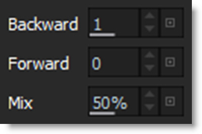
By default, Onion Skin is set up to display a mix to the previous frame.
Backward
Displays frames before the current frame.
Forward
Displays frames after the current frame.
Mix
Sets the Onion Skin mix value.
Snapshot
Captures the image in the Viewer so that it can be compared with other nodes or Viewer modes using Toggle Snapshot, Vertical Split, and Horizontal Split snapshot modes.
Toggle Snapshot
Cycles between the snapshot and the current image.
Vertical Split
Compares the snapshot and the current image using a vertical split. Move your cursor into the image area over the split line and when the cursor changes to a double-arrow, click and drag to move the split. Depending on the image, the split line may not be obvious, so triangular sashes on the outside of the image help you find it.

Horizontal Split
Compares the snapshot and the current image using a horizontal split. Move your cursor into the image area over the split line and when the cursor changes to a double-arrow, click and drag to move the split. Depending on the image, the split line may not be obvious, so triangular sashes on the outside of the image help you find it.

Blend Amount
Blend Amount, which is only available in the Depth and Morph nodes, appears when a blendable view mode is selected.
In Morph, it appears when View A/B is selected and in the Depth node, it is displayed when the depth map is viewed. Clicking the Blend Amount icon pops up a slider that can be moved from 0 to 100. You can also click and slide on the icon instead of using the slider.
Display Options
The Display Options icon reveals the color management options which remain visible as long as it is enabled.

Silhouette uses the OpenColorIO (OCIO) standard originally developed by Sony Pictures Imageworks for its color management. You can load custom color configuration files and custom LUTs, apply color space conversions, as well as use other controls for fine tuning. Silhouette includes a set of preset color profiles, plus you can configure and use your own by specifying one in the Color Management > OCIO Configuration preference.
For a more detailed explanation of OpenColorIO, including generating LUT’s and suggested workflows, please visit http://opencolorio.org/.
Note: The color management functionality provided in the Display Options is for display purposes only. The color profiles, LUTs, and colorspace conversions applied in the Viewer do not affect the rendered image.
OCIO Color Management
Colorspace
Sets the input colorspace of the scene. Silhouette automatically tries to determine the colorspace based on the data in the file and other information from the header. If a colorspace can’t be detected, linear will be selected.
Roles
Different shows may require different color pipelines and to aid artists in how they manage color workflows in Silhouette, OCIO Roles are utilized. Roles appear at the top of the colorspace menu, but all of the colorspaces in the OCIO config file are still accessible and are grouped below the roles.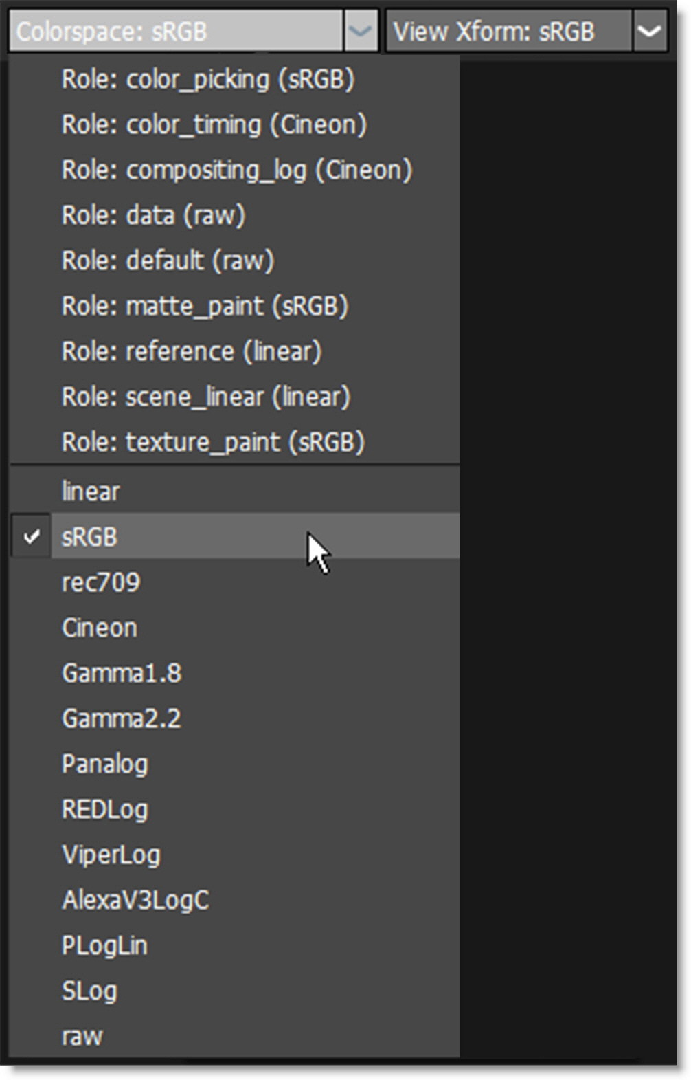
Custom role names for different colorspaces can be assigned so it is obvious to artists which colorspace they should use. For instance, roles can be set up for compositing, color timing or matte painting. Artists still have access to the colorspace options they've always had, but now the roles can act as a quick way to understand and select the color workflow of a particular show.
Roles
• color_picking: sRGB
• color_timing: Cineon
• compositing_log: Cineon
• data: raw
• default: raw
• matte_paint: sRGB
• reference: linear
• scene_linear: linear
• texture_paint: sRGB
Colorspaces
• Linear, sRGB
• rec709
• Cineon
• Gamma 1.8
• Gamma 2.2
• Panalog
• REDlog
• ViperLog
• AlexaV3LogC
• PLogLin
• SLog
• Raw
Adding Roles
Enter the role, family, and name of the role in the roles section of the OCIO config file located at <install_dir>\resources\ocio\silhouette-default.
Here is an example of the roles from an Aces OCIO config file.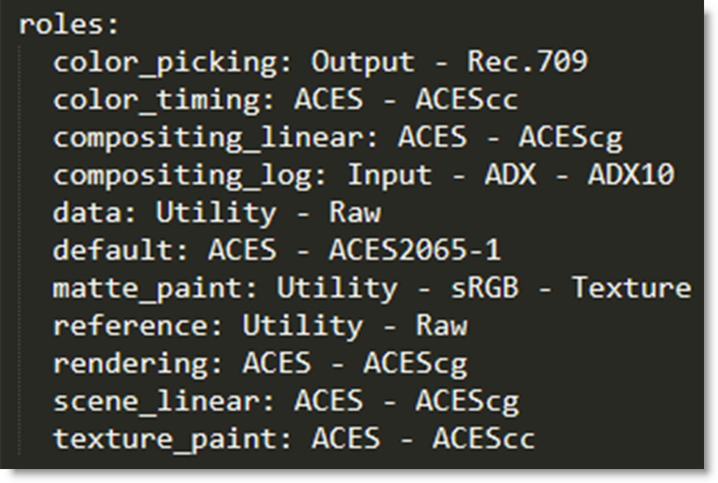
The first part of the role defines the name of the role displayed in Silhouette and the second part describes the colorspace family and name. The family and name determine which colorspace is associated with the role.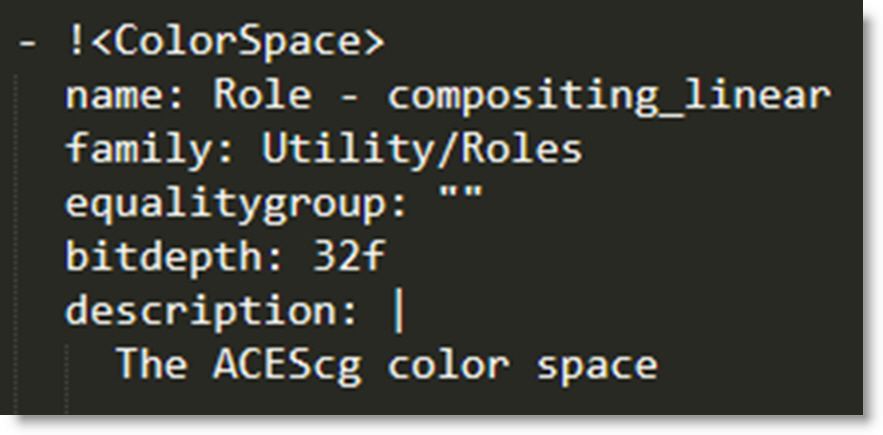
Display
If you are using a custom OCIO configuration with multiple Display options, the Display pop-up menu appears for you to choose the colorspace of the display. The default OCIO configuration only has one display option. Additional devices can be added in a custom configuration and will show up in this menu.
Note: When there is only one Display option, the Display pop-up menu is hidden.
View Transform
Sets the transform from the input scene’s colorspace to the display colorspace. Select a colorspace that matches your display device. You can select from sRGB, rec709 or None.
LUT
Applies a custom OCIO LUT to the scene. See the Appendix H - OCIO LUTS chapter for a detailed list of supported LUTs.
Choose
Select a LUT.
Note: Selecting a LUT disables the Colorspace and View Transform controls. Use the OCIO LUT node to simultaneously utilize both the OCIO Viewer controls and a LUT.
Clear List
Clears the LUT list.
Gain
Adjusts the brightness of the image in F-stops. Gain is applied before the display transform.
Gamma
Adjusts the gamma of the image. Gamma is applied after the display transform.
Go to the Color Management tutorial to see how it works.
ROI (Region of Interest)
ROI (Region of Interest) crops the image in the Viewer to a user defined size and can be animated. This is especially useful when you only need to work within a smaller region of a larger image as it will use less memory and process faster. If expanded, the ROI will display overscan pixels which can then be manipulated.
Go to the Region of Interest tutorial to see how it works.
ROI Controls
Once the ROI icon is activated, the ROI controls appear above the Viewer.
ROI Keyboard Shortcuts
Shortcut | Action |
|---|---|
Click-drag bounding box points | Scales the ROI |
Click-drag bounding box | Positions the ROI |
Ctrl/Cmd-Shift-drag | Draws a new ROI |
Enable
You can toggle the ROI effect on and off by clicking on the Enable icon.
ROI Manual Input
If you click on the numeric field to the right of the ROI label, the fields become editable. Just click in the field you want to edit, type in a number and press the Set button.
Animating the ROI
Enable the animate icon and change the position or size of the ROI at various frames.
Set ROI to Current DOD
The Set ROI to Current DOD icon automatically sets the ROI to match the size of the source’s DOD (Domain of Definition). If the source’s DOD is larger than the session, the ROI will expand revealing the overscan pixels which can then be manipulated.
Note: The Transform > DOD node can change the DOD of any source.
Reset
Resets the ROI to the session size.
ROI Notes
1 Rendering EXR Files
• The ROI becomes the data window and the session becomes the display window.
• The ROI window is rendered along with the ROI window’s coordinates. This will allow you to automatically composite the ROI window into its proper location.
2 Rendering Non-EXR Files
• Disable Crop/Pad in the Output node to render the ROI for non-EXR files.
Surface
The Surface icon displays the selected layer’s surface when in Transform mode. By default, the surface is set to the corners of the layer and in Transform mode, adjust the surface corner points with the on-screen controls. Use the Layer > Set Surface action to automatically set the surface to the boundary of the selected shape.
The following tasks can be achieved using a Surface:
• Create Corner Trackers from Layer Surface
When using Create Corner Trackers from Layer Surface, point trackers are created from the Surface corner points.
• DOD
When the Data output of a node with a layer surface is plugged into the DOD > Data input and the layer is selected, the DOD is automatically set to the bounding box of the surface.
• Transform Node > Insert
Use the Layer > Surface corner points to set the insert corner-pin.
Magnifier
The Magnifier opens a magnification window at the bottom right corner of the Viewer and displays a zoomed area around the cursor location. It is useful for precise control point, tracker and paint placement. The Magnifier is available in the Reshape and Tracker tools as well as Paint.

Masks
Masks aid you in determining what will be projected on film or shown on television by adding reticles and or a variable opacity mask to the Viewer.
The following aspect ratio’s are supported: 1:66, 1:78, 1:85, 2:35 as well as Safe Action for video. When an aspect ratio is selected from the Mask pull-down menu, the mask settings defined in the Viewer Preferences are activated. See the Viewer Preferences section for more information.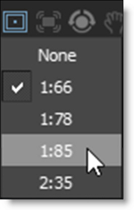
Creating Custom Masks
In the Silhouette/resources folder of your installation, there are two files: formats.xml and masks.xml.
You can add your own custom masks to the masks.xml file. The rectangle values are multiplied by the image width/height to figure out where the mask should be placed. For example, Safe Action is a 90% rectangle, so the border is .1, .1, .9, .9 (i.e. 10%, 10%, 90% 90%) of the image size.
You associate certain masks with certain formats by adding a “Mask” entry to the formats in formats.xml. You can add any number of masks to each format. These masks will be available in the mask selector in the Viewer, depending on the session format.
Note: You can't associate masks with “custom” session formats. Instead, you should add a new format to your formats.xml file if you have an odd format you want to use with masks.
Stabilize
The Viewer is stabilized based on the selected layer’s tracking data.

Rotate
Activates Viewer rotation mode. Shift-Ctrl/Cmd-R toggles the Viewer rotation mode. Rotating the Viewer can facilitate rotoscoping and painting.
Adjust Rotation
Once Rotate is enabled, the Adjust Rotation editing control becomes available. Adjust Rotation allows you to click and drag in the Viewer to set the angle. Shift-R toggles the rotation editing mode on/off.
Adjust Rotation allows you to click and drag in the Viewer to set the angle. Shift-R toggles the rotation editing mode on/off.Go to the Viewer Rotation tutorial to see how it works.
Overlay
Toggles the display of overlays which are lines, shapes or objects that Silhouette superimposes over the image. 0, the number zero, toggles the overlay.
Notes
Displays object notes with callout lines in the Viewer. The object name is listed along with the note.
Clicking on a note’s text selects the object and a callout line is drawn from the note to the object.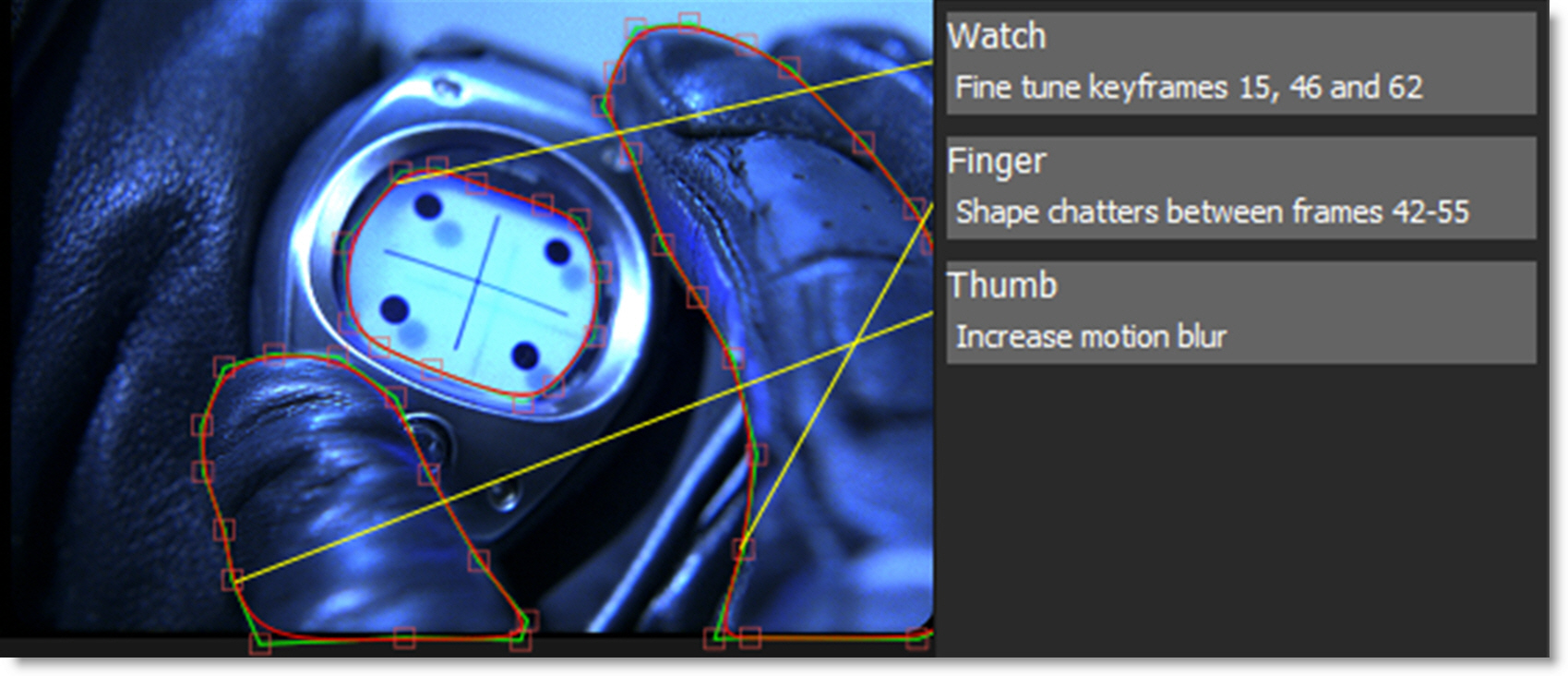
Viewer Preview
When an alpha channel is present, the Viewer has a variety of display options.
RGB Straight
Shows the entire image regardless of the alpha channel.
Over Black (Shift-0)
The image appears in areas of the alpha channel over a black background.
Over Gray
The image appears in areas of the alpha channel over a gray background.
Over White
The image appears in areas of the alpha channel over a white background.
Over Checkerboard
The image appears in areas of the alpha channel over a checkerboard background.
View Channel
Displays various combinations of the red, green, blue and alpha channels.
Selecting Channels
Clicking on the Red, Green, Blue or Alpha buttons solo that channel as a gray scale image. The horizontal white bar above the RGBA buttons quickly toggles the display of the image back to full color mode.
Solo Channels
Alt-R/G/B/A toggles the red, green, blue and alpha channels on and off.
Note: A white outline is displayed around the currently selected channel’s icon.
Alpha Display
Cycle Alpha
Either press the Alpha button (to the right of the blue button) or the A key to cycle the state of the alpha display. Pressing once superimposes the alpha channel over the image. Pressing a second time displays the alpha channel over black. Hitting it again shows only the color image.
Note: To view a shape’s alpha channel, you must first set the View to Output before pressing the Alpha button or the A key.
Display Alpha - No Overlay
Shift-A toggles the View to Output, superimposes the alpha channel over the image and deactivates the Overlay. Pressing Shift-A again returns the Viewer to its previous state.
Display Roto Node’s Output Alpha
Alt+O toggles the view mode to Output and displays the alpha. Pressing Alt-O again returns the Viewer to its previous state.
Invert Alpha (;)
The ; key inverts the alpha in the Viewer. When inverted, the alpha pot in the View Channel icon changes from white to black.
Alpha Mix
The numeric entry box next to the RGBA buttons controls the opacity of the alpha channel when it is superimposed over the image.
Go to the Using the RGBA buttons in the Viewer tutorial to see how it works.
Aspect Ratio
Activates pixel aspect ratio correction in the Viewer as defined in the session settings. For instance, this lets you view Cinemascope ratio images as they would appear when projected.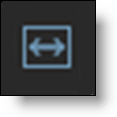
External Monitor
Displays Silhouette on an external broadcast monitor when using a Blackmagic I/O device.
Zooming and Panning
Sets the zoom factor for the image.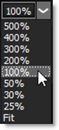
25%-500%
Choose from one of the preset zoom percentages. 100% displays the image at its actual size at a ratio of one image pixel to one screen pixel.
You can also zoom the image using the scroll wheel on your mouse, the + or = keys to zoom in, and the - key to zoom out or press Space Bar-Shift and move the mouse up to zoom in or down to zoom out.
Fit
Either pressing the F keyboard shortcut or selecting Fit from the zoom pop-up window will display the image as large as possible within the Viewer window.
Home
You can either press the H keyboard shortcut or double-click the middle mouse button to set the image to a 100% zoom level and center it in the Viewer.
Center Selected Object
Press Ctrl/Cmd-F to center the select object in the Viewer.
Go to the Viewer Navigation tutorial to see how to zoom and pan the Viewer.
Viewer Keyboard Shortcuts
Shortcut | Action |
|---|---|
F1 | The composite workspace is displayed |
F2 | The Viewer is displayed full screen |
F3 | The Viewer and Timeline are displayed |
F4 | The Viewer and Trees window are displayed |
F5 | The dual monitor workspace is displayed |
0 | Toggles the display of overlays which are lines, shapes or objects |
1-7 (Number Keys) | Switches the Viewer > View menu |
~ | Cycles through the update modes |
A | Cycles the display between the full color image, the alpha channel superimposed over the image, and the alpha channel by itself |
Shift-A | Toggles the View to Output, superimposes the alpha channel over the image and deactivates the Overlay |
Alt-R/G/B/A | Toggles the red, green, blue and alpha channels on and off |
; | Inverts the alpha in the Viewer |
Alt-O | Toggles the Roto node’s view mode to Output and displays the alpha. Pressing Alt-O again returns the Viewer to its previous state. |
Shift-Ctrl/Cmd-R | Toggles the Viewer rotation mode on/off |
Shift-R | Toggles the Viewer rotation editing mode on/off |
Shift-0 | Premultiplies the image in the Viewer by the alpha |
Alt-] | Cycles to next node in the Node pop-up menu |
Alt-[ | Cycles to the previous node in the Node pop-up menu |
Viewer Pan/Zoom Keyboard Shortcuts
Shortcut | Action |
|---|---|
Middle-mouse drag | Pans the image |
Space Bar-move mouse | Pans the image |
+ or = | Zooms the image in |
- | Zooms the image out |
Shift-Middle-mouse drag | Zooms the image in and out |
Scroll wheel | Zooms the image in and out |
Space Bar-Shift-move mouse up/down | Zooms the image in and out |
F | Fits the image in the Viewer |
H or Middle-mouse double click | Centers the image in the Viewer at 100% |
Ctrl/Cmd-F | Centers selected object in the Viewer |
‘ | Opens a context menu over pen/mouse location |