Working with Stereo Images
Creating a Session Using Left and Right Clips
1 Load left and right clips and create a session based on the left view.
2 In the Trees window, add a Roto node from the Nodes > Image group and connect it to the source node.
3 Add a Paint node after the Roto node.
4 Double-click the source node in the Trees window to view and edit it.
5 In the Node parameters, select the right clip in the Stream > Right pop-up menu.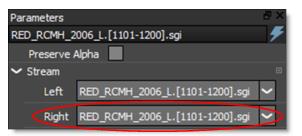
6 Single-click in the center of the Roto node in the Trees window to view and edit it.
You are now ready to create shapes.
Creating a Session Using Stereo EXR Files
Since stereo EXR files contain both the Left and Right Views within one file, they are automatically connected to the Left and Right views.
Using Merge Views to Create Stereo
You can use the Image > Merge Views node to merge input images into a combined left, right and depth view. This bypasses the source node’s Stream parameters.
Stereo Roto
1 Above the Viewer, make sure that the Left View icon (Shift-1) is highlighted. 
When using a stereo EXR file or when left and right clips have been assigned in the Source node’s Stream > Left and Right parameters, the Viewer displays additional view modes.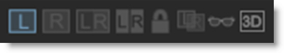
The Left View icon displays the Left View in the Viewer.
The Right View icon displays the Right View.
The Left/Right View icon displays both the Left and Right Views simultaneously.
When shapes and layers are created, they will be associated with either the Left or Right View.
2 Create a shape around an object and keyframe as necessary.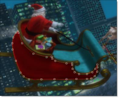
Since the Left View is selected, the shape is automatically associated with the Left View and an L is displayed for it in the Object List’s View icon.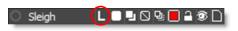
3 Select the shape if it is not already selected and from the Edit > Stereo menu, choose Duplicate > New Layer.
The shape and all of its keyframes from the Left View are duplicated to the Right View in a new layer and the two shapes are linked together. The newly duplicated shape and layer have a R displayed for it in the Object List’s View icon signifying that it is associated with the Right View.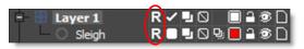
Note: Clicking on the View icon in the Object List toggles which view the object is located in.
When using shapes inside of a transformed layer, you can duplicate the layer instead. This will copy the layer along with its transform data into the other view, copy any unlinked stereo children into it and then link the shapes. You can stereo duplicate one layer at a time using this method.
4 Select the Right View (Shift-2).
You probably noticed that the shape in the Right View does not line up with the object it is associated with. This is because the Right View is offset from the Left View to create the stereo effect. However, you can use the Stereo Align tool in conjunction with a layer to negate the offset between the Left and Right Views.
5 In the Object List, click on the layer that was created for the duplicated shape.
Clicking on the layer makes it the active layer and a check appears.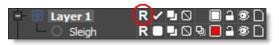
You are now ready to align the two views.
6 Select the Stereo Align icon (Shift-4) above the Viewer.
When activated, Stereo Align uses a negative mode which inverts one of the views and mixes it with the other. This creates an embossed effect when similar image areas are not aligned.
7 To perform an automatic alignment, press Shift-Alt and click on the image feature that you would like to align.
or
8 Click and drag the move cursor that appears to align the views in the area of your shape. You can also Ctrl/Cmd-drag for finer accuracy. When similar image features are perfectly aligned for the object you are rotoscoping, you will see a solid gray color.
Note: The amount you move the view in Stereo Align mode is stored in the Stereo Offset parameter of the active layer which is set to animate by default.
If you need to align vertically (not common), you can either use the Up/Down Arrow keys or press the Shift key while clicking and dragging the move cursor in the Viewer.
Note: You can automatically align without being in align mode by pressing Shift-Alt and clicking on an image feature.
9 If needed, you can keyframe the Stereo Offset
10 Deactivate Stereo Align mode and the shape will be aligned in the Right View.
If the object you are rotoscoping moves through various depths, you will want to keyframe the Stereo Offset using the Stereo Align mode at various frames.
Note: If you are rotoscoping objects at different depths, place them in separate layers so that different Stereo Offsets can be set on a per layer basis.
11 Adjust the shape keyframes as needed for the shape in the Right View.
12 Select the Left/Right View (Shift-3).
In the Left/Right View, the Viewer displays both the left and right clips.
Note: When the Edit In Both Views icon is enabled, shapes are edited in both views simultaneously. When disabled, shapes in the left or right view are edited individually.
13 To change whether the Left and Right Views are arranged either horizontally or vertically in the Viewer, press the Stereo Split Mode icon.
In the Left/Right View, selecting one of the linked shapes in the Viewer selects the other as well, and you can edit both shapes at once. If you only want to work on one shape at a time in the Left/Right View, just make sure that only one of them is selected in the Object List.
Linking Shapes
As an alternative to using Edit > Stereo > Duplicate or Edit > Stereo > Duplicate > New Layer as outlined in the previous exercise, shapes of the same type and the same number of control points can be linked together for stereo rotoscoping. Once linked, the two shapes can be simultaneously selected and edited in the Left/Right View.
1 Select the Left View (Shift-1) and create a shape.
2 Choose the Right View (Shift-2) and create a shape of the same type and number of control points as the one you just created in the Left View.
3 Press the Left/Right View icon (Shift-3) above the Viewer.
4 Select both shapes in either the Object List or directly in the Viewer.
5 From the Edit > Stereo menu, choose Link.
The two linked shapes can now be simultaneously selected and edited when in the Left/Right View.
Stereo Paint
In general, painting on stereo images is the same as painting with single images.
1 Double-click the Paint node in the Trees window to view and edit it.
The stereo view mode determines whether you are painting on the Left View, Right View or both the Left and Right Views at the same time.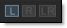
2 Select the Left View (Shift-1).
Paint is applied to the left view only.
3 Choose the Color brush (Shift-C).
4 Paint on the image in the Viewer by pressing and dragging with your pen or clicking and dragging with your mouse.
5 Select the Right View (Shift-2) and paint on the image.
Paint is applied to the right view only.
6 Select the Left/Right View (Shift-3).
7 To change whether the Left and Right Views are arranged either horizontally or vertically in the Viewer, press the Stereo Split Mode icon.
8 Paint on the image.
Paint is applied to both the left and right views simultaneously when the Edit In Both Views icon is enabled. When disabled, the left or right view is painted individually.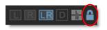
When painting on both views simultaneously, the location of the paint in the Right View will be offset slightly from the Left View. To paint on both the Left and Right Views at the same time and in the same location, you will need to add a layer and then use the Stereo Align mode to line up the two views.
9 Click Add Layer in the Object List.
Two layers are added since you are in the Left/Right View.
10 Delete one of the layers since you only need one of them.
11 Select the remaining layer.
Immediately after selecting the layer, a check appears which means that it is the active layer.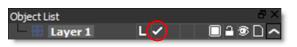
You are now ready to align the two views.
12 Select the Stereo Align icon (Shift-4) above the Viewer.
When activated, Stereo Align uses a negative mode which inverts one of the views and mixes it with the other. This creates an embossed effect when similar image areas are not aligned.
13 To perform an automatic alignment, press Shift-Alt and click on the image feature that you would like to align.
or
14 Click and drag the move cursor that appears to align the views in the area where you will be painting. You can also Ctrl/Cmd-drag for finer accuracy. When similar image features are perfectly aligned for the object you are painting, you will see a solid gray color.
Note: The amount you move the view in Stereo Align mode is stored in the Stereo Offset parameter of the active layer which is set to animate by default.
If you need to align vertically (not common), you can either use the Up/Down Arrow keys or press the Shift key while clicking and dragging the move cursor in the Viewer.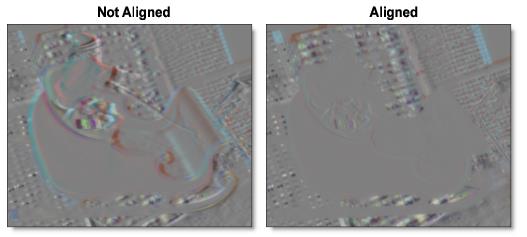
If the object you are painting moves through various depths, you will want to set the Stereo Align setting on each frame.
Note: You can automatically align without being in align mode by pressing Shift-Alt and clicking on an image feature.
15 Deactivate Stereo Align mode.
16 Paint on the image again.
Once aligned, painting with the Left/Right View activated will paint on the same location of the image in both views.
17 Paint some more frames in the clip.
As frames are painted, markers are shown in the Timebar to provide a visual display of which frames are painted. Red markers are displayed for painted frames in the Left View, blue markers for the Right View and green markers for frames painted in both the Left and Right View.
Duplicating Strokes from One Stereo View to Another
By default, strokes only get painted into their original view when they are played back. The Duplicate feature in the Auto Paint window will duplicate strokes from one view to another on the current frame.
1 In a stereo session, make sure that the Left View icon (Shift-1) is highlighted above the Viewer.
2 Paint strokes in the Left View.
3 In the Auto Paint window, select the strokes to be duplicated.
4 Select Duplicate L>R in the Auto Paint window.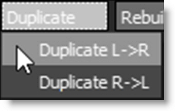
The paint strokes are duplicated from the Left to the Right View.
Note: If a layer with a stereo offset is selected prior to duplicating, the stereo offset is taken into account when duplicating the strokes.
Stereo Morphing
1 Select the Left View (Shift-1).
2 Create a morph just as you would if working with mono images except make sure that all shapes are in layers. This will allow you to easily adjust the Stereo Offset later.
Once you have created shapes for the A and B rolls, specified shape correspondences and have animated the distortion and transparency, you can move onto to handling stereo specific issues. The first step is to duplicate all of your shapes and layers to the right side. You can do this by using the Edit > Stereo > Duplicate feature.
3 Select a layer and from the Edit > Stereo menu, choose Duplicate. Repeat this for each layer in the Left view as this operation can only be done one layer at a time.
Edit > Stereo > Duplicate copies the layers, its shapes and all of their keyframes from the Left View, duplicates them in the Right View and links them together. The newly duplicated layer and shapes have a R displayed for them in the Object List’s View icon signifying that it is associated with the Right View.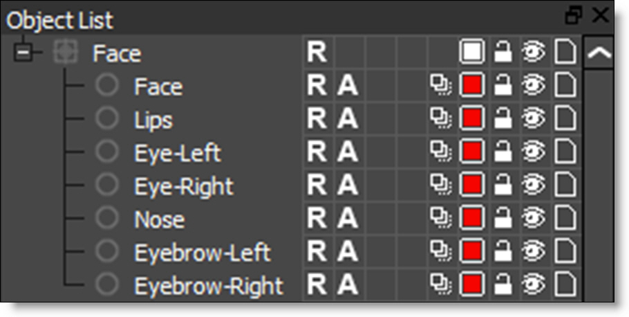
Note: Clicking on the View icon in the Object List toggles which view the object is located in.
4 Select the Right View (Shift-2).
You probably noticed that the shapes in the Right View do not line up with the objects associated with them. This is because the Right View is offset from the Left View to create the stereo effect. However, you can use the Stereo Align tool in conjunction with a layer to negate the offset between the Left and Right views.
5 In the Object List, click one of the Right view layers.
Clicking on the layer makes it the active layer and a check appears.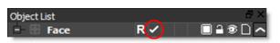
You are now ready to align the two views.
6 Select the Stereo Align icon (Shift-4) above the Viewer.
When activated, Stereo Align uses a negative mode which inverts one of the views and mixes it with the other. This creates an embossed effect when similar image areas are not aligned.
7 To perform an automatic alignment, press Shift-Alt and click on the image feature that you would like to align.
or
8 Click and drag the move cursor that appears to align the views in the area of your shape. You can also Ctrl/Cmd-drag for finer accuracy. When similar image features are perfectly aligned for the object, you will see a solid gray color.
Note: The amount you move the view in Stereo Align mode is stored in the Stereo Offset parameter of the active layer which is set to animate by default.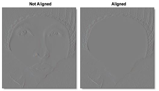
Note: You can automatically align without being in align mode by pressing Shift-Alt and clicking on an image feature.
If the object you are morphing moves through various depths, you will want to keyframe the Stereo Offset at various frames.
9 Keyframe the Stereo Offset if necessary.
10 Deactivate Stereo Align mode and the shapes will be aligned in the Right View.
Note: If you are morphing objects at different depths, place them in separate layers so that different Stereo Offsets can be set on a per layer basis.
11 Adjust the Stereo Offset for all of the Right View layers.
If you need to make shape adjustments in the Right View, viewing the A or B roll will give faster interaction than View > Output.
12 Adjust the shape keyframes as needed for both the A roll and B roll shapes in the Right View making sure to select View > A or View B as appropriate.
13 Select the Left/Right View (Shift-3).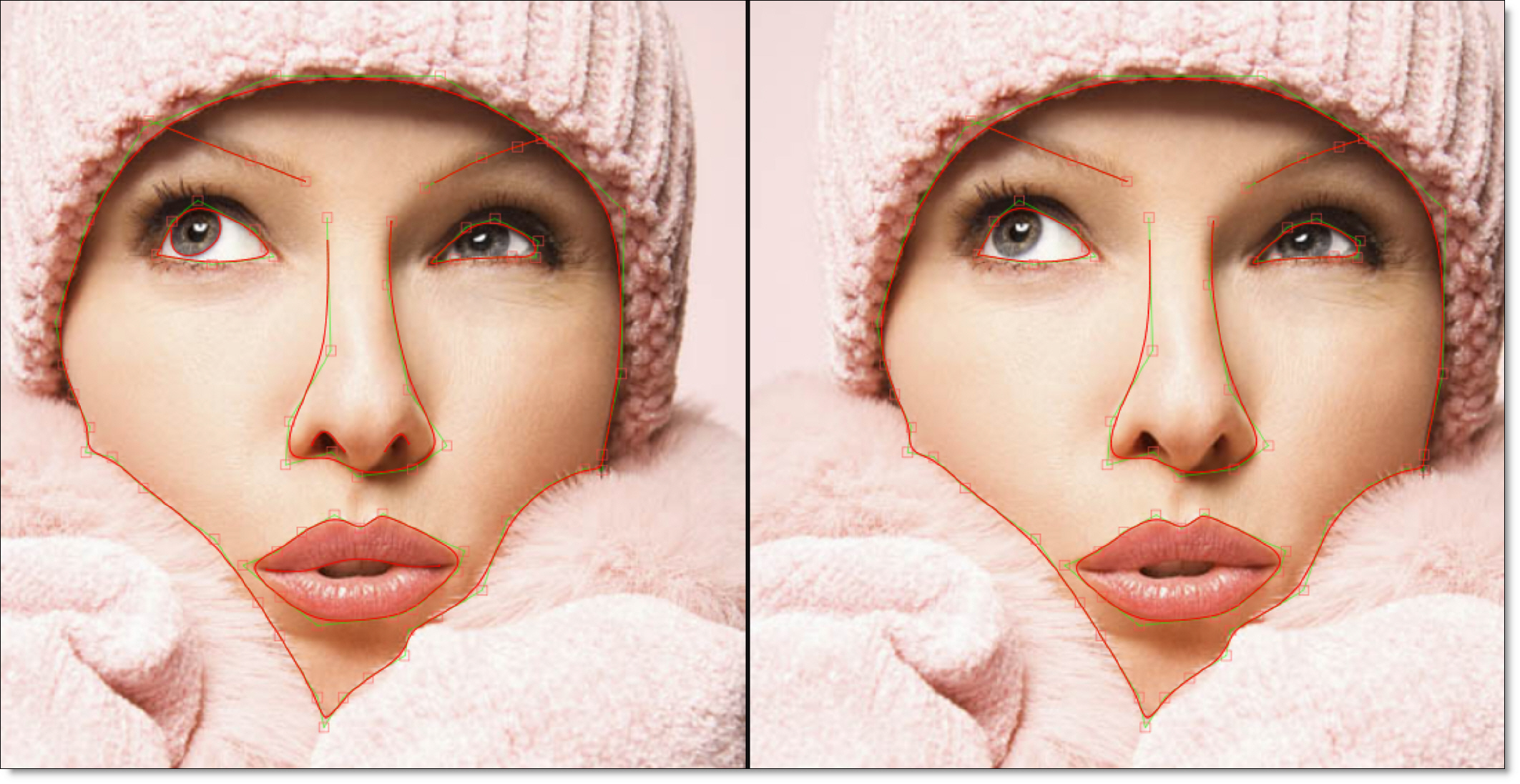
In the Left/Right View, the Viewer displays both the left and right clips and their shapes.
14 To change whether the Left and Right Views are arranged either horizontally or vertically in the Viewer, press the Stereo Split Mode icon.
In the Left/Right View, selecting one of the linked shapes in the Viewer selects the other as well, and you can edit both shapes at once. If you only want to work on one shape at a time in the Left/Right View, just make sure that only one of them is selected in the Object List.
15 Change the View to Output and press 0 to turn off the shape display. This will allow you to see the image better.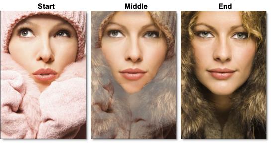
16 Press the Play button.
Silhouette will render each frame of the left and right clips. If you have enough RAM to fit the clip into memory, it will playback in real time once it is completed.
Using the 3D Preview
Silhouette provides a 3D Preview window for displaying the stereo image.
1 Click the 3D Preview icon or press Shift-6.
If you have multiple monitors, the 3D Preview opens full screen while on a single monitor system, it opens centered and smaller.
2 When the 3D Preview opens, right-click on it and select your display type.
3 On a single monitor system, right-click on the 3D Preview and select Fullscreen.