Shape Based Warping
Image warping can take place on a stills as well as moving images. Warping can be used to enhance or exaggerate facial features, adjust sizing of image elements, create talking animals or any other type of image deformation.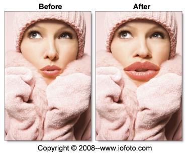
Create Source and Target Shapes
A source and target shape are required for a warp.
1 Load some source footage and create a session
2 In the Trees window, add a node from the Nodes > Warp tab and connect the A input to the source node.
3 Single-click in the center of the Morph node to view and edit it.
4 Select View > A.
Viewing the A side while creating and editing shapes will give faster interaction than View > Output.
5 Create source and target shapes.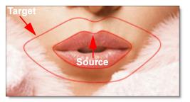
6 If necessary, keyframe the position of both the source and target shapes.
Joining Shapes
Joining shapes specifies the direction of a warp. Joining shapes is done with the Correspondence tool. When two shapes are joined, correspondence points define where elements in the source shape match to elements in the target shape.
1 Select the Correspondence (C) tool in the Toolbar.
2 Click the source shape and drag a line to the target shape.
3 When the cursor is over the target shape, release the mouse button to join the shapes.
As the shapes are joined, one correspondence point is created on each shape and a line connects them.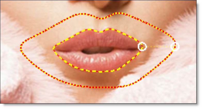
4 Move the correspondence points to match up to like features. For instance, in the image above, the points are placed at the corner of the mouth in both shapes.
Adding Correspondence Points
When a new shape is created, Silhouette adds a single correspondence point on the shape. It is best to add and position these points so that logically similar features are connected together. Correspondence points serve as guides that define the location of identifiable areas on a shape.
1 With the Correspondence tool active, select a shape.
2 Alt-click the shape where you want to place the new correspondence point.
Correspondence points determine how to transform the areas of the image defined by your source and target shapes.
3 Place correspondence points at key positions on the shape.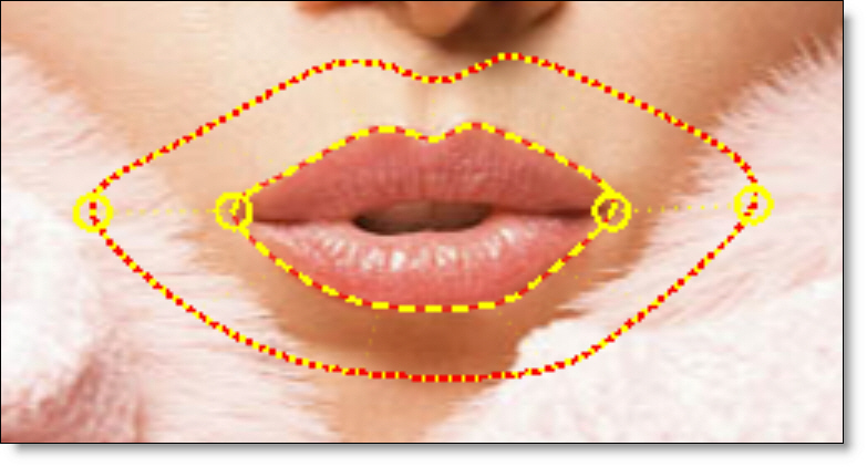
Setting the Distortion
The Distortion parameter warps the image from the source to the target shape.
1 Change the View to Output.
The Output view is where you can see the actual warp.
2 Select the Node parameters tab.
3 Set the Distortion to 0 at the start frame and 100 at the end frame.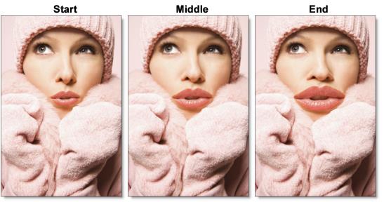
4 For faster interaction, you can use a lower quality proxy image by using the Proxy pull-down menu above the Viewer.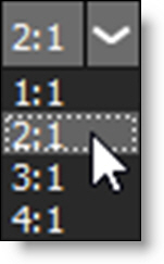
Barrier Shapes
Besides creating shapes to define areas that warp and morph, you can also use shapes as ways of restricting movement beyond certain parts of the image. These shapes are called barrier shapes and tack down an area and keep it stationary. Any unjoined shape will serve as a barrier.
1 Use a barrier shape (an unjoined shape) to tack down an area and keep it stationary.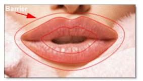
In the example above, the barrier shape will prevent any movement outside of the shape. Compare the results below.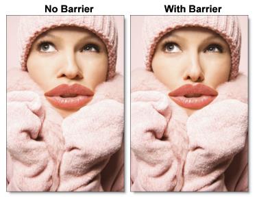
The barrier shape has successfully pinned down the image outside of its boundaries.
Previewing the Warp
1 Press the Play button in the Timebar.
Silhouette will render each frame in order. If the view mode is set to Output and you have enough RAM to fit the clip into memory, Silhouette will play the results in real time once it is completed.
Note: If the view mode is set to A Warp, the results of each frame are not cached into memory.
2 If you see artifacts in the preview, go to the Node tab and change the Precision to Normal first and then Better if you still see artifacts.
Note: By default, the precision or quality of the warp is set to Draft.
3 For faster processing, you can use a lower quality proxy image by using the Proxy pull-down menu above the Viewer.