Rendering
Frame by frame rendering is necessary in Silhouette. When using the plug-in, rendering can occur in the host application or in Silhouette which renders directly to the file system.
Plug-in
An Output node that does not have an output file path is automatically created and inserted at the bottom of the tree at the time of project creation.
Note: If multiple output nodes are present, the host application will use the first Output node it finds that does not have an output path set. Otherwise, it'll use the first Output node.
1 If one does not exist, add an Output node after the nodes that you would like to render in the Trees window.
2 Exit Silhouette and return to the host application.
3 Render using the host application’s rendering system.
You can also render directly to the file system from within Silhouette by following the steps below.
Standalone
1 In the Trees window, add Output nodes after the nodes that you would like to render.
2 In the Output node, set the file format type.
The format setting allows you to select from various file formats. We currently can save to the following file formats: Cineon, DPX, GStreamer, IFF, JPG, OpenEXR, PNG, SGI/RGB, TIFF and TARGA.
3 Enter the path and file name for the rendered file in the File field. You can either type in the path and name in the File field or click the Browse icon on the right.
As far as filenaming is concerned, you only have to type in a name as periods, hash marks for padding and file extensions are not required unless you want to manually enter them. See below.
4 If you choose to manually enter the file padding and extension, the filename should have 3 things:
• The image name.
• # for the frame placeholder.
• An extension: .exr = exr files, .cin = Cineon files, .tif = Tiff files, etc.
Therefore, if you enter a name something like test.####.exr,. Silhouette will render out test.0001.exr, test.0002.exr, etc. You can confirm how the files will be formatted by looking in the Output node’s Sample field. The Sample field displays all of the files that will be produced by the node.
Note: Some formats have render options that can be customized. For instance, GStreamer has a dedicated Options menu for setting the codec, quality, resolution, etc.
5 Choose the appropriate channels to render. You can choose from RGB, Alpha and Depth.
6 If you are rendering a stereo project, select whether you want to render the Left, Right or Both the Left and Right Views simultaneously using the Views pop-up menu.
7 Press the Render button, Ctrl/Cmd-R or Select Session > Render Session.
The Render Options window opens.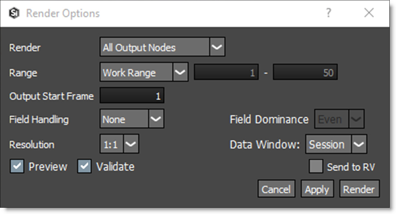
8 Choose whether to render All Output Nodes or just the Selected Output Nodes.
Note: Output nodes have to be selected for the Selected Output Nodes option to work.
9 Select one of the Data Window options to determine the size of the rendered images.
• Session: Renders the session size.
• ROI: Renders the ROI (Region of Interest)
• DOD: Renders the DOD (Domain of Definition)
Note: For non-EXR images, disable Crop/Pad in the Output node to render the DOD or the ROI.
10 Select the range of frames to render.
11 Enable Preview and select Render.
The Preview window opens and displays each rendered image as well as render statistics. Pressing the R, G, B, and A buttons toggles viewing of the respective channels while C displays the RGB channels.
Rendering the Automatic Data Window
The Automatic Data Window rendering option looks at the alpha channel and determines the data window from that. Then, it writes only the pixels in the data window to an EXR file. For SXR files, it writes the combined data window between the two views. This greatly speeds up loading these files into a compositing system.
1 To render the EXR data window based on the alpha channel, set OpenEXR as the file format in the Output node.
2 Enable the Automatic Data Window option.
Silhouette will now look at the alpha channel to determine the data window and render only the pixels in the data window to the file.
Rendering EXR Multi-Part Files
The Output Multi-Part node renders EXR multi-part files.
1 From the Image tab, add an Output Multi-Part node to the Trees window.
2 Connect the output of different nodes into the Output Multi-Part node’s inputs.
If you would like more than the 4 default inputs, more can be added.
3 Right-click on the Output Multi-Part node and select Add Input. Right-click on an input port to remove it. You can add as many inputs as you want, but the inputs will get smaller.
If there is more than one input, each output part name is appended with the upstream node's name.