Lens Correction
Powered by Silhouette’s Roto tools, Lens Correction locates and undistorts lens distortion. To compute lens distortion, you need an image with one or more distorted straight lines or a distortion map, sometimes called a UV map or ST Map. The Lens Correction node is built on shared technology from Mocha Pro’s Lens Module.
Line Calibration
1 Load a source clip and create a session.
2 In the Trees window, add a Lens Correction node from the Nodes > Warp group and connect it to the source node.
A common way to generate accurate distortion models is to photograph a calibration grid, which provides a source of long straight lines.
3 If you are using a calibration grid, connect it to the Calibration Reference input.
4 Single-click in the center of the Lens Correction node to view and edit it.
5 If you are using a calibration clip, select View > Calibration Reference, otherwise leave the View set to Output.
6 Using the integrated Roto shape tools in the Toolbar, create at least one open shape over a curved line that should be straight. To finish drawing an open shape, select the Reshape tool or press the Esc key.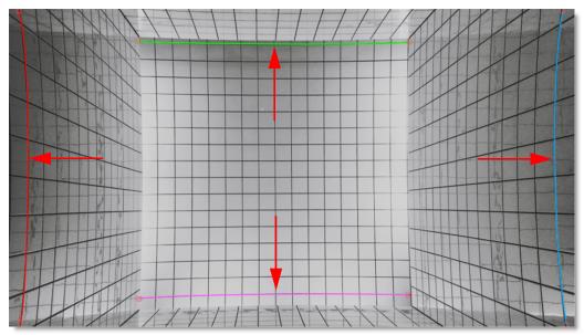
• Choose lines that exhibit the most distortion, typically those reaching towards the edge of the image, and not pointing towards the center.
• Make sure the lines cover the majority of the image, otherwise the distortion may be computed incorrectly in the areas where there are no lines.
7 Once lines are defined, click the Node tab to view the Lens Correct parameters.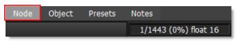
8 In the Camera Model pop-up menu, select a model. Usually 1-Parameter or 2-Parameter are good choices.
• 1-Parameter
Use when a small amount of distortion is present.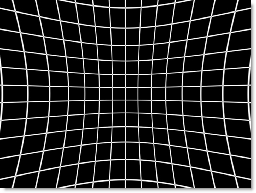
• 2-Parameter
Use the 2-Parameter radial distortion model if 1-Parameter doesn’t capture all the distortion in the image. This distortion model is often used when there is a wave or irregularity in the lens.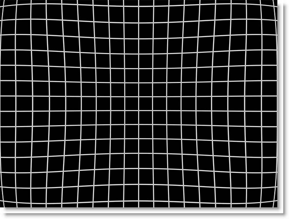
9 Make sure the View is set to Output.
The Correction pop-up menu determines whether the image is undistorted (the default) or distorted. You would use Distort if you are returning the image back to its original distorted state after previously undistorting it.
10 Click the Calibrate button to compute and apply the lens correction.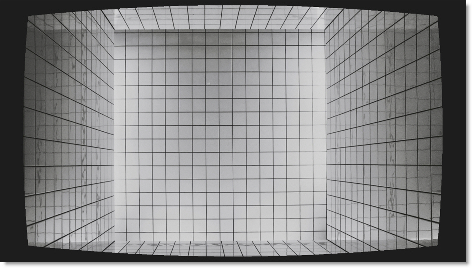
Using Distortion Maps
Distortion maps can be used to correct lens distortion.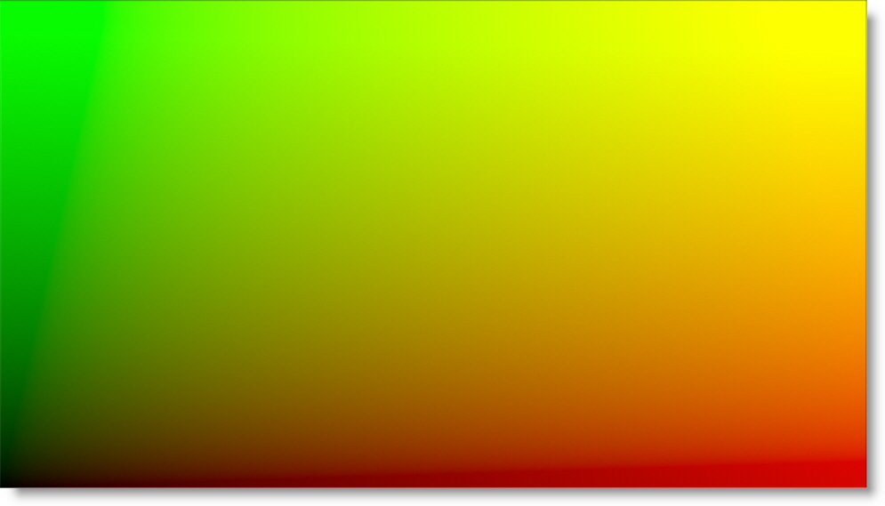
Note: Distortion maps must be 32 bit float RGB.
1 Load source and distortion map clips and create a session.
2 In the Trees window, add a Lens Correction node from the Nodes > Warp group and connect it to the source node.
3 Connect the distortion map into the Distortion Map input.
4 In the Camera Model pop-up menu, select Distortion Map.
The lens is automatically corrected based on the distortion map.
Rendering Distortion Maps
The Lens Correction node can output Undistort and Distortion Maps.
1 Connect an Output node to Lens Correct’s Undistort Map output (middle output).
2 Connect an Output node to Lens Correct’s Distortion Map output (right output).
3 Make sure your Session is set to 32 bit float and select a file format that supports 32 bit float such as EXR.
4 In the Render Options window, make sure you select Data Window > DOD and for non-EXR images, also disable Crop/Pad in the Output node.
This will ensure that if the lens correction created a DOD larger than the Session size, the rendered file will also be larger.
Go to the Lens Correction node for more information.
Manual Correction
1 Load a source clip and create a session.
2 In the Trees window, add a Lens Correction node from the Nodes > Warp group and connect it to the source node.
3 Single-click in the center of the Lens Correction node to view and edit it.
4 In the Camera Model pop-up menu, select a model. Usually 1-Parameter or 2-Parameter are good choices.
5 Set the View to Grid.
A grid is displayed over the input image so you can adjust the distortion parameters manually.
6 Adjust K1 for 1-Parameter or K1 and K2 for 2-Parameter until the grid lines match the curves in the input clip.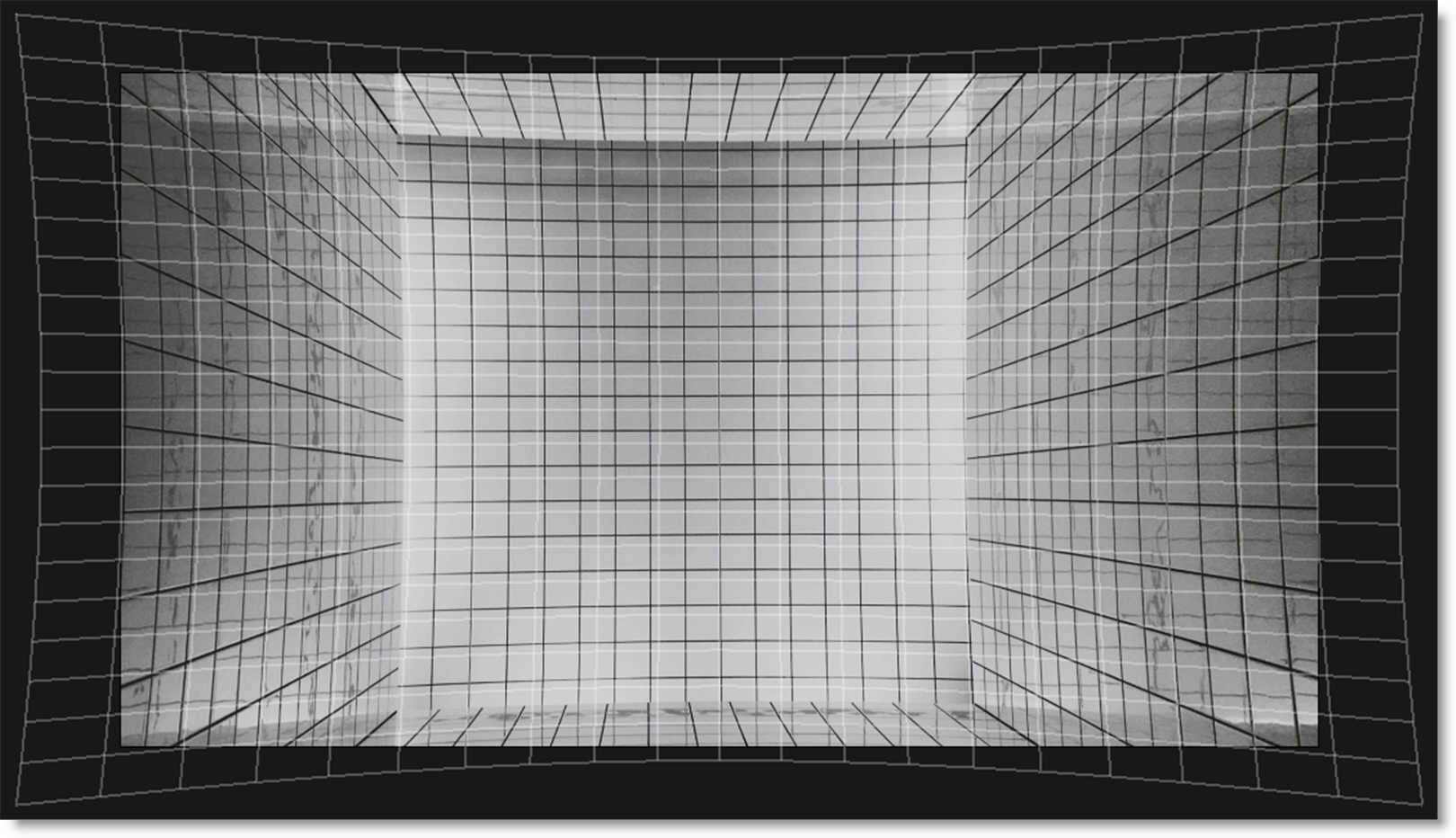
7 Set the View to Output to see the resulting lens correction.